-
What is the current status of overfire air/air staging technology for fossil fuel fired furnaces?
Date posted:
-
-
Post Author
dev@edge.studio
1. Background
Furnace air staging also known as [GLOSS]Separated OverFire Air[/GLOSS]([GLOSS]SOFA[/GLOSS]), or two-stage combustion, is a well established technology for [GLOSS]NOx[/GLOSS] reduction based in the air staging principle (see CF 56). Specifically, it extends the residence time in an atmosphere of low oxygen availability to encourage the formation of N2 in preference to NOx.
However, increasing the residence time at low oxygen availability also has the effect of reducing combustion efficiency, and unless other measures are taken (coal fineness improvements, etc.) an increased level of carbon in ash is inevitable.
SOFA is equally applicable to both wall and tangentially fired plant. It also can be combined with LNB’s to achieve more effective NOx reductions levels.
2. How does this process works?
Key parameters in the SOFA process are:
- The stoichiometry in the reducing zone. Essentially lower stoichiometries give rise to lower NOx emissions.
Depending upon coal quality, the best NOx reductions that can be achieved when the primary zone stoichiometry varies between 0.8 and 0.9. This level of primary zone stoichiometry is called ”deep staging”. Appreciable NOx reductions can still be achieved at a primary zone stoichiometry of 1.0 (“shallow staging”).
- The residence time within the primary zone: longer reducing zone residence times lead to lower NOx emissions.
- Mixing of the [GLOSS]OFA[/GLOSS] (OverFire Air): this is addressed by injector design. In general, poorer mixing gives rise to lower NOx and higher carbon in ash as a result of an effective increase in the residence time under oxygen deficient conditions.
3. How is the overfire air separation achieved?
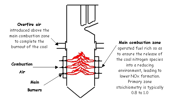
In the context of wall firing, SOFA usually involves the diversion of a proportion of the main combustion air from the burners to separated overfire air injectors located at a discrete elevation above the main burners, (see figure1).

Figure 1: Schematic of a furnace designed with the Separated Overfire Technology
However, in retrofit situations where access to the air ducts and OFA windbox may be a constraint, it may be necessary to locate the OFA nozzles in the furnace sidewalls. There have been limited instances where two elevations of OFA injectors have been used.
Injection of the OFA can be accomplished in a number of ways:
- Via the top tier of burners – this is a special case of the “Burners Out of Service” [GLOSS]BOOS[/GLOSS] technology. The burners act as crude, unoptimised OFA injectors, and significant NOx reductions have been achieved in this low cost system, mainly in oil-fired plant. For modern plant required to meet current emission standards, this option is not considered to be a practical proposition.
- Via simple openings in the furnace walls. This option is derived from tangential firing technology, and would typically comprise a rectangular opening divided into a number of compartments (typically 2 or 3). At full load all compartments would be in use, but as load is reduced, individual compartments would be closed so as to maintain the OFA injection velocity.
- Via circular twin-stream injectors. This is the favoured approach of a number of equipment suppliers (including Mitsui Babcock, Foster Wheeler, Babcock and Wilcox, Babcock Hitachi). In this arrangement the OFA is split into two separate streams, a central unswirled core, which provides a strong forward momentum to ensure penetration of the jet to the centre of the furnace, and a swirled outer annulus, which enhances the lateral dispersion of the OFA across the furnace width. Most injectors of this type have the capability of adjusting the flow split between the swirled and unswirled fractions, and the level of swirl imparted. By this means there is significant scope for optimising the mixing of the OFA during site commissioning tests. OFA is taken from the windbox air supply via hot ducting to the injectors. A damper controls the overall level of OFA, but in some installations individual damper control of each injector allows the possibility of biasing the flow between nozzles.
In tangentially fired units the OFA is introduced to the corners of the furnace as follows:
- Local to the burners but the angle of injection is biased towards the walls to delay the mixing with the coal as well as providing a protective envelope – this is known as “off set” air.
- Through OFA nozzles immediately above the burners – “close-coupled OFA” ([GLOSS]CCOFA[/GLOSS]).
- Through OFA nozzles some distance above the burners – “separated OFA” (SOFA).
Sources
[1]Michelfelder S & Leikert K. The Stage Mixing Burner and Operating Results of Pulverised Coal Burners for Low NOx Emission. VGB Kraftwerkstechnik 60 (2) 95-103. (1980)
[2]Lam KB, Wilkinson PJ & King JL. Application of Low NOx Axial Swirl Burners to Castle Peak B Power Station. 9th CEPSI Conference – Hong Kong. (1992)
[3]Macphail J, Rhine JM & Hughes M. The Demonstration of Gas Reburning Technology on a 600 MWe Boiler at Longannet, Scotland. (1997)
[4]Macphail J, Rhine JM & Hughes M. Proceedings “4th International Conference on Technologies and Combustion for a Clean Environment”, Scotland. (1997)
[5]Hesselmann G & Chakraborty R. Coal Over Coal Reburn – The Applicaton of Pilot Scale Test Results to Utility Plant Design. Power-Gen Europe 98. (1998)
