-
What is a grey gas?
Date posted:
-
-
Post Author
dev@edge.studio
1. Emission and absorption by gases
The gaseous atmosphere in any fuel-fired furnace or combustion plant participates in the overall interchange of radiation. In fossil-fuel fired plants, carbon dioxide and water vapour are the most important emitters and absorbers of thermal radiation. At the molecular level, emission and absorption occurs because of quantum transitions in the vibrational and rotational energy levels of these [GLOSS]heteropolar molecule[/GLOSS]. As a result, radiation emission and absorption occurs at discrete bands or wavelengths in the electromagnetic spectrum. There are bands in the spectrum within which there is no radiation absorbed or emitted. These are often referred to as ‘windows’ in the spectrum, and can play a significant role in the interchange of radiation between surfaces. Radiation of this nature is termed ‘non-grey’ to distinguish it from [GLOSS]grey body[/GLOSS] radiation normally associated with surfaces.
The calculation of thermal radiation exchange in furnaces is very complex owing to the non-grey properties of the combustion gases. To simplify calculations, the gases may often be represented as an equivalent [GLOSS]grey gas[/GLOSS]. The grey gas approximation is also useful if there is particulate material in the flame (soot or mineral matter), when radiation resembles that from a surface, with a more continuous emission and absorption spectrum.
2. What is a grey gas?
Like a grey surface, a grey gas is a radiating and absorbing gas whose [GLOSS]emissivity[/GLOSS] (and [GLOSS]absorptivity[/GLOSS]) do not vary with wavelength. Emissivity is given by the formula:
e = E/Eb (1)
where E is the radiative flux emitted by the gas and Eb is the radiative flux that would be emitted by a [GLOSS]black body[/GLOSS] at the same temperature.
e has a value between 0 and 1. A perfect emitter (black body) has an emissivity of 1.
Since, in practice, all gases are non-grey, a grey gas is a theoretical concept only, which is applied to simplify engineering calculations of thermal radiation in furnaces. However, by integrating the spectral emissivity of a real gas, it is possible to arrive at a total emissivity value for the equivalent ‘grey gas’.
3. What does grey gas emissivity depend on?
The emissivity of a grey gas can be derived by considering a simple beam of radiation passing through an incremental slice of gas. The beam is attenuated in proportion to its intensity (I), and the distance traversed through the gas, thus:
(- dI)/I = K dx (2)
where, K (m-1) is the grey gas [GLOSS]attenuation Coefficient[/GLOSS] or [GLOSS]extinction coefficient[/GLOSS], which is equal to the fractional attenuation of the beam per unit distance. For gases, it is usual practice to express K as the product of an [GLOSS]absorption coefficient[/GLOSS] kg (m-1atm-1) and the [GLOSS]partial pressure[/GLOSS] p (atm) of the absorbing gas; thus:
K = kgp (3)
Assuming the gas is homogeneous (i.e. K is independent of distance x), integration of this equation over a thickness L of gas gives the [GLOSS]transmissivity[/GLOSS] (t):
t = I/Io = exp(-KL) (4)
where Io is the incident intensity and I the leaving intensity. This is known as the Bouger-Lambert law. The radiation that is not transmitted is absorbed. The absorptivity (a) is therefore given simply as:
a = (1 – t) = {1 – exp(-KL)} (5)
The same relationship between gaseous emissivity and absorptivity applies as for surfaces. For a grey gas, the [GLOSS]total absorptivity[/GLOSS] and emissivity are equal and thus:
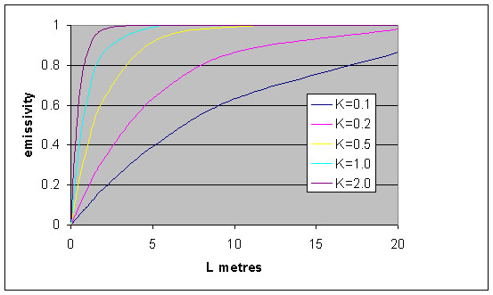
e = {1 – exp(-KL)} = {1 – exp(-kg pL)} (6)
In Figure 1, a plot of equation (6) shows that the emissivity of a grey gas increases as the thickness of the gas increases. Emissivity asymptotically approaches a value of 1 at high values of the product KL. The emissivity is also seen to increase significantly with increase in partial pressure of the absorbing/emitting gas, since K is the product of the absorption coefficient and pressure.
4. The mean beam length
Thus, in order to determine the emissivity of a grey gas, it is necessary to know the beam length for radiation. There are many possible (non-parallel) paths of different length for a beam of radiation in a given gas volume. For simple engineering calculations it is often useful to determine a ‘[GLOSS]Mean Beam Length[/GLOSS]’ Lm. The mean beam length is a function of the shape of the gas volume as well as its size. The following simple formula, derived by Hottel and Sarofim [3], provides a very useful approximation to many geometries:
Lm = 3.5 (V/A) (7)
where V is the volume of the gas and A is the total bounding surface area. More exact formulae exist for specific shapes.
5. Introducing the mixed grey gas model
Non-grey gases in furnaces can be mathematically represented by a mixture of grey gases. This is a very powerful technique and has been widely applied in ZONE models. One of the grey gases is assumed to have an emissivity of zero (a zero attenuation coefficient, K) and this represents the ‘windows’ in the spectrum, i.e. parts of the electromagnetic radiation spectrum where a gas does not absorb. The other grey gases take account of parts of the spectrum where absorption or radiation occurs. The mixed grey gas model will be described in more detail in CF44.
Sources
[1] Robert Siegel & John R.Howell, Thermal Radiation Heat Transfer, 3rd Edition,
1992, Hemisphere, ISBN 0891162712
[2] W.A.Gray and R.Muller, Engineering Calculations in Radiative Heat Transfer, Pergamon Press, 1974
[3] Hottel and Sarofim , Radiative Transfer, McGraw-Hill, 1967.