-
What are the principles behind the use of multi-directional probes for velocity measurements in furnaces?
Date posted:
-
-
Post Author
dev@edge.studio
1. Background
The principles behind the use of unidirectional velocity probes were presented in a linked combustion file
(CF11). Such unidirectional probes have to be oriented in the flow direction in order to give a true value of velocity. Frequently the direction of the velocity is not known and its determination is important for the measurements (e.g. in flames with swirl).
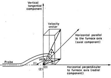
The velocity is then characterised by two angles f
and d and a scalar magnitude V, or by its three components in a system of reference axes associated with the probe and the
installation. In addition to these three unknowns, the value of the local static pressure is often required. These four values can be measured with a direction sensitive impact tube.

Figure 1. Reference co-ordinates for velocity measurements
2. Principle
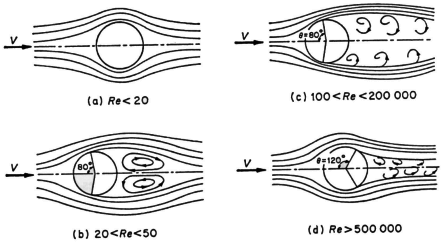
The distribution of pressure around an obstacle placed in a uniform flow depends upon the Reynolds number, as well as the magnitude and direction of the velocity.

Figure 2. Reynolds number dependence of flow around an obstacle
In the domain where most furnace measurements are made (Reynolds number between 100 and 60 000, flow of type (c)), it has been established experimentally that the reduced velocity field Vlocal/Vo around a sphere, placed in a uniform flow with velocity Vo varies only slightly with Reynolds number.
In other words, according to the Bernoulli Theorem, the pressure, divided by the velocity squared, on the surface of a sphere is similar in form when the flow direction does not change. The pressure
Pn, measured at a point n, is therefore given by the expression:


and, if


where
Vn is the velocity at point n (m/s)
kn is a factor that only depends upon the velocity direction characterised by the angle
qn
between the axis and the pressure tapping n, or alternatively by two angles f
and d in a system with axes fixed with respect to the installation.
When there are a sufficient number of
pressure tapping, n, the unknown Vo, ps, f
and d in the system of equations above can be calculated if the function kn(f,d) is known.
It is known that in the vicinity of the forward stagnation points the law is close to that corresponding to potential flow:
![]()
However, there is a rapid deviation from this law, when qn
increases, and the law becomes completely different in the vicinity of and downstream of the points of separation. In addition the condition of the surface of the sphere can influence the factor kn;
also the flow is never perfectly symmetrical around the probe and it is never possible to perfectly reproduce a
probe. Consequently the law kn(f,d)
must be determined experimentally for each instrument.
3. Applications
Various designs of 5-hole Pitot probes have been used at the IFRF, depending on the particular measuring conditions such as hot or cold models, pulverised coal or oil furnaces.
For studies in cold models, finely constructed uncooled probes of small dimensions are used.
For measurements in the furnace, the probes need to be more robust, cooled by water or constructed out of refractory material and protected from condensation of water or oil vapour, and from the deposit of particles which can alter the characteristics of the probe and block the pressure hole (see
CF143).
Sources
Industrial Flames, General Editors, Prof. J M Beér and Prof. M W Thring
Vol 1, Measurements in Flames by Chedaille and Y Braud.
