-
How do I construct a pressure tapping for velocity measuring probes in furnaces?
Date posted:
-
-
Post Author
dev@edge.studio
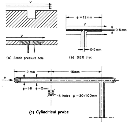
If a cavity is made in the wall of a duct through which fluid is flowing, as shown in the figure below, the pressure set up inside this cavity is the static pressure of the surroundings, provided that no vortex is formed inside the cavity.
1. Static Pressure Tappings

The dead fluid filling the cavity may be considered as an element of the wall and it is sufficient to connect manometer to the cavity in order to measure the static pressure.
If a burr is formed at the edge of the hole, or if the wall in the proximity of the hot is not perfectly smooth, the local flow conditions will be altered and consequently the measured static pressure. It is important therefore that the edges of the hole should be perfectly smooth (Prandtl considered that a small rounding of the hole was permissible) and the surface of the wall in the vicinity of the hole should have no projections perpendicular to the flow direction.
In practice it is preferable to construct separately the pressure tappings in a carefully finished plate which is then fitted to the wall rather than making a hole directly into the wall.
For measurement of the static pressure at a point in a flow, a disc, based upon the principles described above, can be used. This is equivalent to an element of the wall and should be as thin as possible. The disc must be aligned in the plane of the flow direction and in order to make this adjustment a yaw meter is sometimes fitted near the edge of the disc (Fig. (b)).
If the disc is facing upstream or downstream the flow, the cylindrical static pressure (Fig (c)), is more convenient for use and is insensitive to errors of orientation of ±5°, but it is less precise in turbulent flows. When this probe is placed at an angle q to the flow direction the pressure reading is too low and for a tube with a hemispherical head, the static pressure pS can be determined from the following relation:
![]()
where pSm is the measured static pressure, r is the flow density, V is the magnitude of the flow velocity vector, and Ks is a positive constant.
2. Total Pressure
The total pressure (dynamic + static) is that pressure measured at the upstream stagnation point of an obstacle.
It is, therefore, sufficient simply to make a hole and connect this to a manometer.

Since the velocity at this stagnation point is zero, the condition of the surface in the vicinity of the pressure tapping does not have to be particularly smooth.
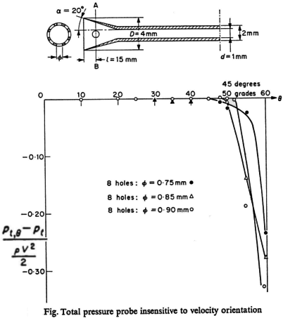
The influence of the ratio d/D has to be fixed for each type of instrument.
For large values of this ratio the probe is less influenced by the direction of the flow and probes such as those shown in the figure along side can be used to carried out measurements where the angle q is large.
A probe with a very small diameter (~ 2 mm) will give a measurement which is virtually at a point and this is particularly useful in turbulent flows.
