-
How do I apply the Rayleigh Criterion to suppress organ pipe Combustion Oscillations?
Date posted:
-
-
Post Author
dev@edge.studio
1. Background
In CF295 we discussed the general features of “vibrations maintained by heat” as they were understood by the late 1800s. In the interim we have come a little farther or, perhaps, just a little more explicit in our understanding. To understand one of the practical means of eliminating combustion-driven oscillations, we need now to add the concept of “burning delay time,” a concept that as far as the author is aware was not dealt with by John William Strutt (3rd Baron Rayleigh), at least not explicitly.
2. Burning Delay Time
”[GLOSS]Burning delay time[/GLOSS]” is the period of time that elapses between the release of an 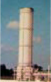 eddy-like glob of reactant from an orifice until that glob actually reaches the [GLOSS]flame front[/GLOSS] and burns.
Think of a premixed conical flame like that of a Bunsen burner. It is conical because the jet velocity exceeds the [GLOSS]flame speed[/GLOSS]. If you increase the flame speed by changing the mixture, or decrease the jet velocity by turning down the burner, the flame gets shorter, which means the burning delay time gets shorter. Eventually, when the flame speed is the same as the jet velocity, the flame retreats all the way back to the nozzle. There is no delay time at all. The moment a glob of reactant emerges, it burns.
Now suppose that, for some reason, the nozzle sees a sinusoidally varying backpressure. What happens? Naturally, the reactant emerges at the same sinusoidally varying rate. Think of it as a train of progressively larger-than-normal reactant globs followed by progressively smaller-than-normal globs and let’s follow the fate of one of those larger-than-normal globs of reactant.
Depending on the delay time, it takes a while before that larger-than-normal glob burns to release its larger-than-normal amount of heat, which produces a larger-than-normal volume expansion, which produces a pressure pulse. In free space this doesn’t amount to much. But if it occurs in the limited volume of a combustion chamber, and during a positive half-cycle of the sinusoidally varying backpressure in the combustion chamber, this extra heat release augments the backpressure variation. If not, it suppresses it. By varying the flame speed and jet velocity, the flame can be “tuned” as it were to build up the sinusoidally varying backpressure.
That’s about all there is to it. All you have to do is stick the nozzle into the chamber, tune up the flame, and presto! Combustion-driven oscillation. Naturally it isn’t quite that simple but you get the idea.
You can try for yourself how this works by sticking a common home-plumbing propane torch into a piece of pipe. The pipe or rather the air inside the pipe, as we all know, has “organ pipe” resonance frequencies. To get the vibration going you will have to diddle with the fuel valve a little to tune up the flame. But once you get it going, the sound, the tone of which can be calculated exactly based fundamentally on the length of the pipe, is prodigious indeed.
3. Ground Flare Suppression Examples
Burning Delay Time
Is this merely a cute demonstration or does this happen in real life? On rare occasions it certainly does. Monster organ pipes exist in some refinery and petrochemical complexes. Called “ground flares,” many are about 6m in diameter and about 30m tall. Many years ago one my first encounters with combustion-driven oscillation occurred in just such a unit.
An organ pipe of this length has a very low frequency and of this size can generate a lot of sound. If you consider that the thermal power (MW) being dissipated in such a unit is about 100-million watts, then if even a small fraction is converted to vibrational energy, shaking down the Walls of Jericho or the refractory bricks inside the steel shell is hardly out of the question. For this one the fix was a minor nozzle modification (details proprietary) that changed the burning delay time.
Discussion
We can learn a lot about suppressing standing-wave (“organ pipe”) resonances from this example. “Standing-wave” vibrations are distinguished from “bulk-mode” vibrations in that at any moment in time the pressure inside the enclosure varies with position along the length of the enclosure. By contrast, “bulk-mode” vibrations are those in which the pressure within the enclosure varies but is everywhere the same at any moment in time. Bulk-mode combustion-driven oscillations are discussed in CF297.
Now that we have a physical feel for it, let’s see what a little mathematics tells us about this problem. Since the fluctuating component of heat release provides the sustaining energy when a singing flame occurs, we have to consider how waves form in the fuel supply line. By inserting sinusoidal representations of the pressure and velocity waves into the [GLOSS]Rayleigh Criterion[/GLOSS], one obtains the following condition for maintenance of combustion-driven oscillation:
2(1+β)sin(2ωS/C)sin(ωτ) – β(β+2)cos(ωτ) > 0
The damping is represented by β, ω is the circular frequency, S is the length of the fuel supply line, C is the speed of sound in the supplied gas and τ is the burning delay time.
In practical situations, generally the damping (β) is small and can be neglected. In fact, making the damping large enough so that it cannot be neglected is one of the means of suppressing combustion-driven oscillations. The use of damping for suppression is touched upon below and will be more thoroughly discussed in CF297.
Furthermore, the burning delay time (τ) often turns out to be short enough that sin(ωτ) is always positive. Under these conditions the Rayleigh Criterion becomes even simpler:
sin(2ωS/C) > 0 or sin(4πS/λ) > 0
The wavelength of the standing wave in the supply pipe (λ) is determined by dividing the speed of sound in the supplied gas by the frequency of pulsation in the combustion chamber.
The mathematics suggest that for the common case of a supply line open at the supply end as, for example, in a large receiver or knockout drum, small damping and small burning delay time, vibrations may be sustained whenever the length of the supply pipe is equal to or less than one-quarter of the wavelength in the supplied gas of the vibration in the combustion chamber. On the other hand, if the supply pipe is greater than one-quarter wavelength, up to one-half wavelength, conditions are unfavorable and the vibration evidently should not be maintained. In the next quarter wavelength (i.e., beyond a half wavelength), conditions are again favorable, and so on.
Let us now apply these ideas to the ground flare pictured above. If we express the wavelength in the supply pipe (λ) as the speed of sound in the gas supply (CS) divided by the observed frequency of vibration (ƒ) in the combustion chamber, and remember that the fundamental natural frequency is CL/2L (assuming the combustion chamber is acoustically open at both ends), where CL is the speed of sound in the combustion gases, the Rayleigh Criterion can be related to the physical parameters of this example:
n < (CL/CS)(S/L) < (2n+1)/2; n = 0,1,2, …
Going one step further, the sonic velocities can be related to specific heat ratios (α) and absolute temperature T (K), and the Rayleigh Criterion becomes even simpler.
In the actual case of the ground flare pictured above, the flared gas was a propane/butane mixture (αS ≈ 1.1 and molwtS ≈ 55) supplied at 38oC. The combustion gases can be assumed to be mostly carbon dioxide and nitrogen (αL ≈ 1.3 and molwtL ≈ 30) at a temperature that depends upon the flare load. The length of the supply pipe was approximately 24m and the combustion chamber was 30m tall. Substituting these values, the Rayleigh Criterion expressed in terms of the combustion chamber temperature becomes quite simple:
n2 < TL/224 < (2n+1)2/4; n = 0,1,2, …
Finally then, the mathematics suggest that as the system comes into resonance, the absolute temperature (K) of the combustion gases should just be crossing the value 224n2. In the combustion range of interest, this gives about 620oC (1150°F) as the temperature at which it should begin to be possible to sustain combustion-driven oscillation.
The ground flare pictured above was about 30m tall and 5m in diameter. It was open at the top, and at the bottom there were five vertical slots (about 0.6m wide by 3m high) into which protruded the gas supply pipes, and through which passed the combustion air. In operation, this system occasionally exhibited strong vibrations at a frequency of about 7 Hz. The foregoing application of the Rayleigh Criterion predicted that combustion-driven oscillation should not be sustained until the flue gas temperature reached approximately 620oC, corresponding to a hydrocarbon flow rate about 50% of the maximum design load.
Naturally those were exactly the conditions that marked the onset of combustion-driven oscillation or I wouldn’t be sharing this example with you. But ain’t science wunaful?
Damping
Many years ago my friend George Paul Wilson solved a similar problem by the addition of damping. This was done by a simple though mechanically difficult expedient. A slot was added about 1/3 of the way up the cylinder as sketched here.
The slot had the effect of adding damping to the system and, thus, suppressing the oscillation. The pulsation energy dissipated itself in cyclical in-and-out flow though the slot. The pulsation was still discernable in the sound spectral analyses but thereafter went unnoticed by nearby observers.
4. Hydrogen Reformer Example
Some years ago another instance of combustion-driven oscillation arose in a hydrogen manufacturing plant. The reforming furnace cavity is shaped like that in an electric toaster and has end-to-end standing wave natural frequencies just like the ground flare does only sideways. The steam methane reformer furnace’s performance also fit neatly into the Rayleigh Criterion picture painted above.
Remember that the burner flames can be tuned up by, for example, varying the flame speed and the jet velocity. So how do you do that in a process furnace that operates at constant heat release?
Well, the flame speed increases as you approach stoichiometric combustion; i.e., as you reduce the excess air. And, at constant heat release, the jet velocity decreases as the specific gravity (heating value) increases. Thus, reduced excess air and increased specific gravity lead to shorter burning delay times. So there you have two purely operational means of tuning up the burner flames.
And tune them we did! The frequency and intensity details of the combustion-driven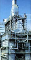 oscillation are not particularly important for the purposes of this discussion. Suffice it to say that at excess oxygen below about 2%, or at specific gravity above about 0.8, the reformer sounded like an idling diesel truck, a monstrous idling diesel truck, and exactly at the frequency of a standing half-wave in the long dimension of the furnace cavity.
Outside this oxygen-gravity envelope the reformer operated normally. The operational solution cost the shareholders nothing. The fix was to red-line the controllable operational parameters so as to avoid the sensitive regime. A more “clever” (i.e., expensive) fix would have been needed if it were impossible to operate within a safe excess oxygen – specific gravity envelope.
With the foregoing as background the reader is now ready for the more detailed discussion of burning delay time alteration, addition of damping and other approaches to suppressing combustion-driven oscillations. These are further elucidated in CF297 on the other manifestation of combustion-driven oscillation, the so-called “bulk-mode” ([GLOSS]Helmholtz resonator[/GLOSS]) response.
Sources
[1] John William Strutt, 3rd Baron Rayleigh, Sc.D., F.R.S., Honorary Fellow of Trinity College, Cambridge; The Theory of Sound, §322h, 1878
[2]Jim Seebold Combustion-driven Oscillation in Process Heaters, IFRF Combustion Journal , 2005
[3] Jim Seebold Combustion-driven Oscillation in Process Heaters. AFRC-JFRC 2004 Joint International Combustion Symposium, October 2004, Maui, HI. Proceedings CD AFRC Technical Secretary (Jordan Loftus (afrcjl@earthlink.net) at the time of writing)
[4] Jim Seebold The Author’s experience