-
What is fluidised bed gasification of biomass?
Date posted:
-
-
Post Author
espadmin
1. Gasification
The energy from [GLOSS]biomass[/GLOSS] can be released in three different ways:
- Direct [GLOSS]combustion[/GLOSS], utilizing as primary or substitute fuel;
- [GLOSS]Fermentation[/GLOSS]/digestion or;
- Gasification.
Biomass gasification is a thermal process converting dry biomass feedstock into a mixture of gases that can be burnt in internal combustion engines and gas turbines. The gasification process takes place in a sealed container with a restricted supply of air. For this reason the process is sometimes known as “gasification by partial combustion”. [1]
2. Atmospheric CFB Gasification
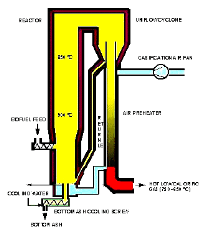
The atmospheric circulating fluidised bed (CFB) gasification system, see the schematic structure in Figure 1, consists of a reactor (where the gasification takes place), a uniflow cyclone (to separate the circulating bed material from the gas) and a return pipe (for returning the circulating bed material to the bottom of the gasifier. [3].

Figure 1: Circulating fluidised bed gasifier. [4]
The fluidising air is fed to the bottom of the bed via an air distribution grid by a high-pressure air fan. The hot fuel gas, after the cyclone, is usually used for air preheating.
The biomass – 20-60% water, 40-80% combustible and 1-2% ash – is fed to the gasifier at the lower part, above the distribution grid. The usual temperature is around 800-1000 °C, depending on the fuel and application. The biofuel first starts to dry and then it is converted into charcoal and tars (pyrolysis). Part of the charcoal flows to the bottom where it is oxidised to CO and CO2, generating heat. At the second stage, heterogeneous (char and gas) and homogeneous (all components are in gas phase) reactions take place. The generated combustible gas escapes through the uniflow cyclone, while the solids (bed material, ash, unburned char) is fed back to the bottom of the gasifier. The combustion of the unburned char generates the necessary heat for the pyrolysis. The circulating bed material serves as a heat carrier, maintaining, stabilising the bed temperature. In normal operation, the fuel feed rate determines the capacity of the gasifier while the airflow controls the temperature. The coarse ash, accumulating at the bottom, is removed by a water-cooled bottom ash screw.
In the uniflow cyclone, compared to the conventional cyclones, the gas and circulating bed material flow in the same direction (uniflow) to the bottom of the cyclone. In small-scale combustion of biomass, the emission control normally involves filtering or scrubbing of flue gases from solid suspended particles.
Typical heating value with 50% moisture content fuel is 2.2 MJ/kg.
Main advantages of utilising the CFB gasifier connected to a combustor:
- The ability to burn low-grade fuels
- High combustion efficiency due to the turbulent mixing of the bed and long residence time in the furnace
- Low SO2 emissions by the reaction of limestone to sulphur at low temperature (850 °C)
- Low CO and CxHy emissions due to turbulence, long residence time and mixing in the cyclone
- Good cycling and load-following capacity, due to the heat transfer being approx. proportional to the load.
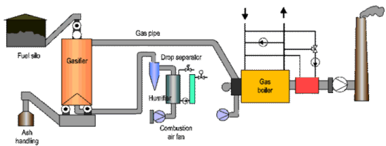
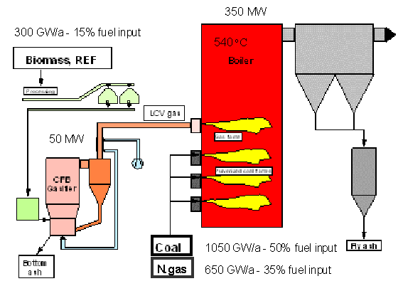
In small-scale combustion of biomass, the emission control normally involves filtering or scrubbing of flue gases from solid suspended particles. A scrubbing and heat recovery plant, Figure 2, combines wet cleaning of flue gases with recovery of heat contained in the gases. The fuel savings are in the range of 10 – 35%. An industrial application of the indirect co-combustion is shown in Figure 3, where the gasified product is the co-fuel to a regular pulverised coal fuel boiler.

Figure 2: Updraft gasifier. Source [5].

Figure 3: Indirect co-combustion by upstream gasification: Foster Wheeler design installed in Kymijärvi (Lahden Lämpövoima Oy) coal and natural gas fired power plant in Lahti. 350 GWh/a (15% of total energy input) biomass and REF, substituting 45.000 t/a coal, resulting in 110.000 t/a CO2 emission. Steam parameters of the once-through Benson boiler: 125kg/s, 540 oC/170 bar/540 oC/40 bar; max. 167 MWe, max 240 MWth. Source [2]
Keywords:
Biomass, fluidised bed, gasification, pyrolysis.
Source:
[1] De Montfort University, http://www.dmu.ac.uk/ln/itc/gastheo.htm
[2] Ree, R.van, Korbee, R., Meijer, R, Konings, T., Aart F. van (2001): Operational experiences of (in)direct co-combustion in coal and gas fired power plants in Europe. Power-Gen Conference, Brussels, February.
[3] Palonen, J. & Nieminen, J. (1999): Biomass CFB Gasifier – Demonstration project: Kymijärvi Power Station at Lahti, Finland. Foster Wheeler Review, summer 1999.
[4] Manjuhan, A., Cotton, J., Ekamabaram, A., Sellakumar, K.M., Palonen, J. (2001): Efficient and clean biomass gasification and combustion technologies for bagasse. Foster Wheeler Technical Papers http://www.fwc.com/publications/tech_papers/powgen/bagasse3.cfm.
[5] Eija Alakangas (1998): Bioenergy in Finland, Review 1998. VTT Energy, Agriculture and Forestry Biomass network (AFB-net), Jyväskylä, FINBIO publications 6. http://194.142.156.236/english/bioenergy_in_finland/index.html
