-
How do I apply the Rayleigh Criterion to suppress Helmlholtz cavity Combustion Oscillations?
Date posted:
-
-
Post Author
dev@edge.studio
1. Background
In CF296, we discussed resonance involving standing longitudinal (end-to-end) waves in a circular cylindrical or rectangular enclosure. But there is another kind of cavity resonance of the type that you get when you blow across the open top of a bottle. We will try to explain this type of resonance and suggest means of suppressing it by discussing a recent real-world example taken from the author’s experience.
2. Bulk-Mode Resonance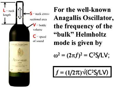
A “bulk-mode” vibration or resonance is one in which the pressure in the responding cavity is, at any instant in time, everywhere the same. This spatial uniformity at any moment in time of pressure variation in the cavity distinguishes bulk mode from standing wave responses to combustion driving that were discussed in CF296.
The bulk-mode response is often called “[GLOSS]Helmholtz resonance[/GLOSS]” after the researcher who identified it. The principle features are illustrated in the picture above. The air in the neck of the bottle acts as a sort of near-weightless cork-like piston to excite the whole cavity into resonance at a well-defined spring-mass frequency that was discovered by Helmholtz.
In the case of a furnace, L would be the length of the stack and S would be its cross-sectional area while V would be the volume of the combustion chamber and C the speed of sound in the furnace gases, strictly speaking the mass-averaged speed of sound. Both in the test furnace and in the monster refinery crude unit furnaces which were afflicted with the phenomenon, plugging the furnace parameters into the frequency formula discovered by Helmholtz produced the right answer; viz., the pulsation frequency that was observed in the field. Ain’t science wunaful?
Hypothesis
In this real-world example, given that the burners discharged into a firebox that is a Helmholtz resonator just waiting to be excited, we had to understand how the “lean premix” ultra-low [GLOSS]NOx[/GLOSS] burners would respond to a sudden change in firebox pressure that arises by whatever means; and under what circumstances the lean premix burners might conspire with the firebox to produce a Helmholtz [GLOSS]combustion-driven oscillation[/GLOSS].
The pertinent features of the lean premix burner are shown in the sketch. A 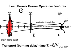 super[GLOSS]stoichiometric[/GLOSS] quantity of air and fuel enter the venturi mixing tube at “0.” At “1” the lean premixed reactants emerge into the firebox with velocity V to burn at “2,” the main flame burst, after traversing a distance l. The transport (burning delay) time τ is equal to l divided by V0-2,avg , the average velocity of the mixed reactants between “0” and “2.” Because the air supplied at “0” is far in excess of that required for combustion of the fuel injected through the [GLOSS]choked nozzle[/GLOSS] at “0,” the flame is virtually transparent and quasi- “[GLOSS]flameless combustion[/GLOSS]” results. The remainder of the fuel required to consume the remaining air is introduced through choked fuel-staged nozzles not shown in the sketch.
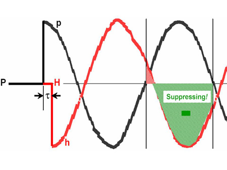
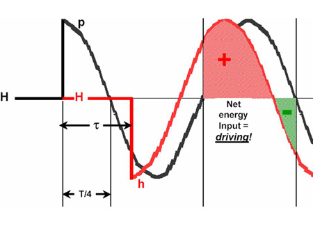
Consider the response of the lean premix burner to a sudden change in firebox pressure P. As shown in sketch a) below, suppose that firebox pressure perturbations are ordinarily suppressed by the quick return of an opposite heat release (volume expansion) perturbation early in the first quarter period of any firebox pressure perturbation that may arise. The steady component of firebox pressure is P while it’s fluctuating perturbation (if any) is p; similarly H is the steady heat release and h is it’s fluctuating perturbation (if any); and τ is the transport (burning delay) time.
We see that in this case most of the fluctuating heat release (volume expansion) would be out of phase with the firebox pressure fluctuation, thus suppressing it, and combustion-driven oscillation would not arise. Even if the burner’s answer were to be delayed by as much as ¼-period of the firebox pressure perturbation as shown in sketch b) below there would still be no net heat release (volume expansion) input into the would-be firebox pulsation as shown below and therefore no driving.
But look at what happens in sketch c). If the burner’s answer were to be delayed by more than ¼-period of the firebox pressure perturbation there would be a net heat release (volume expansion) input and the firebox pulsation would be driven over the next ½-period.
Thereafter driven and clear ½-period intervals of the Helmholtz firebox pulsation period (T) would alternate under the foregoing hypothesis.
a) suppressing
b) neutral
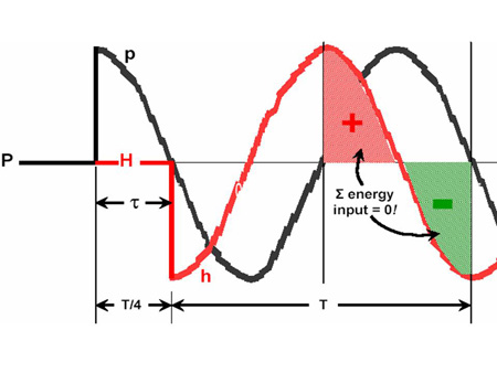
c) driving
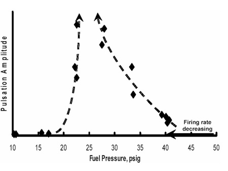
How might the transport (burning delay) time be affected by burner operation? To reduce the burner firing rate the fuel delivery pressure must be reduced to inject less fuel into the mixing tube and also induce less air. The result is reduced mass and volume flow through the venturi mixing tube. This would reduce the average velocity of the reactants and increase the transport (burning delay) time.
In short, according to the foregoing hypothesis, by reducing the fuel pressure it should be possible to “tune” the lean premix burners to produce combustion-driven oscillation.
Test Data
Furnace test data supported the foregoing hypothesis. As shown below, when the firing rate was decreased by reducing the fuel pressure, the combustion-driven oscillation was first “tuned in” and then “tuned out” by continued reduction in fuel pressure.
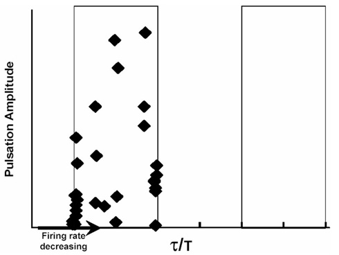
Also shown below is the same test furnace amplitude data plotted as a function of τ/T, the ratio of the transport (burning delay) time and the period of combustion-driven oscillation whenever it occurred. The amplitude data did indeed restrict itself to the first ½-period after the first ¼-period of firebox pulsation. The burner was never operated at a firing pressure low enough to traverse the next clear ½-period to again excite combustion-driven oscillation.
Accordingly, we felt that we had a pretty good handle on how and under what conditions the combustion-driven oscillations arose. Now it was time to conceive candidate fixes.
3. Potential Fixes
Frequency
Shifting the Helmholtz bulk mode natural frequency of the furnace-stack system pulsation quickly came to mind. But because of the long periods involved, none of the possibilities seemed practical.
Changing the dimensions of the giant crude unit furnaces to change the volume of the resonator was out of the question. Changing the furnace temperature would not cater to process needs. A stack extension or a [GLOSS]tunable quarter-wave tube[/GLOSS], though proven fixes in other applications, would have to be ridiculously long and clumsy. In short, shifting the bulk mode Helmholtz response off the range of burner sensitivity was just as quickly rejected.
Furnace Damping
Next to mind came increased damping either in the furnace-stack system or in the 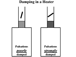 burner. The [GLOSS]Rayleigh Criterion[/GLOSS] is a necessary but not sufficient condition for driving. Another condition is that the acoustic damping not be too large.
Significant acoustic damping is often present in process heaters. The general idea is illustrated in this sketch. There are impedances already provided by the stack damper and by the convection section that may be effective or ineffective depending upon the closure in the case of the stack damper or the tube pitch in the case of the convection section.
Altering the convection section to tighten-up the tube pitch was out of the question. But the stack damper seemed a plausible expedient particularly when it was noticed that the damper was always nearly open at the onset of combustion-driven oscillation. While for process reasons the stack damper cannot be operated at will, perhaps some alteration could be made to enable operation with more closure (damping) at the onset of driving.
Burner Damping
In addition to contributing his Criterion to this investigation, John Strutt (3rd Baron Rayleigh) kindly pointed out that nearly a century and a half ago Prof. Sondhauss solved a similar problem by adding damping to the fuel supply tube.
“His [Sondhauss, 1860] experiments prove the importance of the part taken by the column of gas in the tube which supplies the jet. For example, sound cannot be got with a supply tube which is plugged with cotton in the neighbourhood of the jet, although no difference can be detected by the eye between the flame thus obtained and others which are competent to excite sound.”
In the end, while the team was convinced that damping in the burner would do the trick, filling the several venturis in each burner with sintered fiber metal did not find favor. It would not have been quite as easy as it might seem simply to follow Sondhauss’s ca.140 year old example. The burner venturis would have to be enlarged or the gas pressure increased or both in order to maintain function whilst providing the necessary acoustic damping.
Many other alternatives were tested, some successful and some not. Among the notably successful approaches was active fuel modulation instrumented to cancel the combustion-driven oscillation at its onset. But in the end the team preferred a passive solution of which four seemed practical. Two related to damping while two sought to maintain burner operation out of the sensitive reduced firing rate, increased transport (burning delay) time regime.
1. Increase the stack damping – This can be accomplished by closing the stack damper while sparging with steam in order to maintain the necessary operational draft. This expedient was tried successfully in the test furnace but was not implemented in the field.
2. Increase the resonator damping – This can be accomplished by the well-known AGA advice noted in CF295; viz., “… drill a hole …” and if that doesn’t work “… drill another hole …” or, in our case, provide a variable slot in the side of the furnace. A secondary effect of the slot is to slightly alter the bulk mode Helmholtz resonator frequency. This expedient was tried successfully in the test furnace but was not implemented in the field.
3. Take burners out of service – At lower firing rates this would maintain operation in the remaining burners at velocities in the venturi mixing tubes above the critical velocity marking the onset of combustion-driven oscillation. This expedient was tried successfully in the test furnace and was successfully implemented in the field to eliminate combustion-driven oscillation.
4. Shut off several burner venturis – In the multiple-venturi burners this, too, would maintain the velocity in the remaining venturis above critical. This expedient was tried successfully in the test furnace and was successfully implemented in the field to eliminate combustion-driven oscillation.
Sources
[1] John William Strutt, 3rd Baron Rayleigh, Sc.D., F.R.S., Honorary Fellow of Trinity College, Cambridge; The Theory of Sound, §322h, 1878
[2]Jim Seebold Combustion-driven Oscillation in Process Heaters, IFRF Combustion Journal , 2005