-
How do I apply Laser Sheet Visualisation to industrial scale liquid sprays and soots?
Date posted:
-
-
-
Post Author
Neil Fricker
-
1. Background
Laser Sheet Visualisation ([GLOSS]LSV[/GLOSS]) techniques were developed for application in laboratory bench scale systems. The basic principles of [GLOSS]Mie scattering[/GLOSS] applied to LSV were outlined in a related Combustion File (CF 119). More detailed practical information on the application of these techniques for the analysis of industrial flames is given in CF203.
This Combustion File focuses on the application of the technique to visualisation of industrial scale sprays, typical of those produced by oil atomisers on industrial burners. Application to visualising soot in industrial flames is also illustrated.
2. Experimental arrangement
A typical experimental arrangement for LSV investigation of industrial scale sprays is given schematically in Figure 1, based on the set up applied successfully at the IFRF [1].
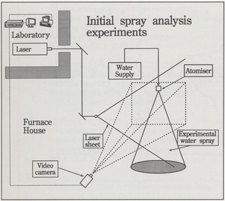
Figure 1: General experimental arrangement for Laser Sheet Visualisation in industrial scale sprays
At the IFRF, the laser sheet is produced by expanding the beam of a [GLOSS]ND:YAG laser[/GLOSS] (wavelength 532 nm) through a cylindrical lens to yield a laser sheet with a nearly constant thickness of 1.2 mm over an area of 1m2[1]. The laser produces pulses with an energy of 190mJ per pulse.
The region of interest is recorded with a black and white [GLOSS]CCD[/GLOSS] camera with a minimum gating time of 1ms synchronised to the pulses (25 to 30 pulses per second) of the laser.
The spatial resolution per pixel is determined by the laser sheet thickness and the camera magnification; it is typically of the order of 1mm3.
3. Typical LSV images from water sprays
Some typical spray images derived from LSV are shown in Figure 2.
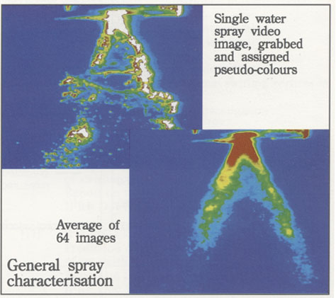
Figure 2: Typical LSV images of a water spray
4. Potential to investigate sprays and soot in oil and gas flames
LSV images of oil spray droplets and soot particles are shown in Figures 3 and 4.
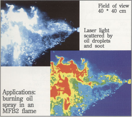
Figure 3: LSV images of droplets and soot in oil flames
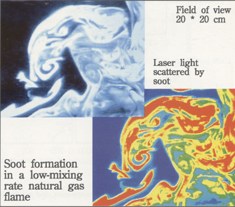
Figure 4: LSV images of soot particles in a natural gas flame
5. Further support
IFRF members wishing for further support in the design or application of LSV systems at industrial scale may request copies of the detailed IFRF reports dealing with this topic.
Sources
[1] P A Roberts (Editor), Research at IJmuiden during the Triennial 1989-1991, IFRF Doc No: K65/y/3