-
A novel, low-cost multifunctional layer for low-temperature polymer electrolyte fuel cells
Date posted:
-
-
-
Post Author
Florence LeeUniversity of Sheffield
-
-
[Editor – IFRF is acting as ‘industrial supervisor’ to two Engineering Doctorate students at the EPSRC Centre for Doctoral Training (CDT) in CCS and Clean Fossil Energy, led by the University of Nottingham in the UK. In this IFRF Blog, Florence C Lee – who is based at the University of Sheffield (a partner institution of this CDT) – outlines the background and scope of her proposed PhD, as well as the experimental investigations she proposes to undertake over the next three years. We wish her every success with her studies and will follow her work with interest, updating IFRF members at key points.]
Background – polymer electrolyte fuel cells
The polymer electrolyte fuel cell (PEFC) – also referred to as the proton exchange membrane (PEM) fuel cell – uses the electrochemical reaction between hydrogen and oxygen producing water to generate a current.
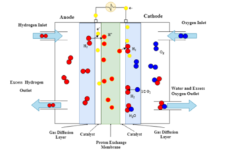
The principles of operation of PEFCs
Referring to the image above of an operational PEFC, humidified hydrogen is fed into the anode-side inlet (on the left hand side), where at the catalyst-gas-membrane interface the hydrogen molecules are ionised to form two H+ ions. The electrons produced by the ionisation of hydrogen enter the external circuit to generate direct current (DC). Oxygen enters the cathode-side inlet and diffuses across the porous gas diffusion layer to the catalyst layer. At the cathode catalyst layer the strongly negatively charged oxygen atoms attract the H+ ions across the proton exchange membrane. At the cathode catalyst layer the oxygen atoms combine with the H+ ions and two electrons from the outside circuit to form a water molecule.
Gas diffusion layers
The gas diffusion layers (GDLs) of the PEFC are sandwiched between the catalyst layer and the gas flow channel on each side of the fuel cell, thus allowing for the transport of reactants and products to and from the catalyst layer as well providing structural support for the catalyst layer. The anode side GDL transports electrons back to the bipolar plate to join the outside circuit, whereas the cathode GDL transfers oxygen to the catalyst and directs water away from the catalyst to the channel. As such GDLs are integral component of the PEFC which control overall cell performance by providing the distribution pathways of the reactant gases and regulating catalyst utilisation.
One of the most important roles of GDLs is to manage water in the liquid and gaseous phases. Correct management of water is crucial in PEFC as insufficient humidification and an excess of water are detrimental to the operation of the cell. The polymer membrane needs to be well humidified for good ionic conductivity across the membrane to reduce ohmic losses whereas a plethora of water can flood the active sites of the catalyst and reduce efficiency. In order to counter flooding of the catalyst, the GDL is coated in a hydrophobising agent, typically PTFE. The transport of water in the GDL is determined by the type of GDL substrate, the quantity of hydrophobic coating, the micro-porous layer coating and the porous structure.
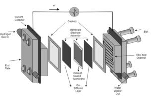
The layers and components of a PEFC
Micro-porous layer
A micro-porous layer (MPL) is often applied to the GDL substrate on the side facing the catalyst layer. It is fabricated from a mixture of hydrophobic agent, polytetrafluoroethylene (PTFE) and carbon black. The MPL was initially applied to reduce contact resistance between the GDL and the catalyst layer, however it has been shown to improve performance by moving liquid water away from the catalyst thus reducing flooding of the active sites.
Scope of research
The criticality of the porous media in optimising the performance of PEFCs is now widely acknowledged. This has spurred on significant research in the past decade focused on broadening the understanding of gas diffusion and catalyst layers. These studies have provided valuable insights and helped further the understanding of the capability of GDLs for mass, heat and electron transport, and the importance of these characteristics on the overall performance of the GDLs. Experimental and numerical methods, aided by visualisation techniques have demonstrated that the transport properties of the GDL are inherently associated with its morphological, microstructural and physical characteristics. These structural and physical characteristics are in turn largely dependent on the materials and the design of GDLs. However, the majority of research into the GDL has been focused on characterisation of the existing GDL materials and designs, where optimisation has been limited to varying the quantity and the application process of these materials in the GDL structure, i.e. numerous studies focus on the effect of PTFE on the mass transport properties of the GDL and how the weight of PTFE in the MPL can be optimised. An extremely small amount of studies sought to improve this by detailed analysis and characterisation of GDLs with alternative wetting agents. It is clear that there is a distinct gap in the exploration of new GDL materials that may improve the efficiency and reduce the cost of PEFCs, thus accelerating the commercialisation of PEFC technology.
Research objectives
The main objective of the research is to improve the performance of PEFCs by improving the transport capabilities of the porous media of PEFCs. Although, liquid water has been the focus of many research groups, its movement within the porous media is still not fully understood and it is still a significant cause of power loss at high current densities. Moreover, almost unanimously in research the porous media of the PEFC are examined individually as components or as the whole fuel cell. It is apparent that there is a lack of studies investigating these components holistically even though their optimum operation depends on each other. As such this study aims to investigate the porous media and the membrane electrode assembly (MEA) as a whole.
The main objective is divided into three sub-objectives: optimisation of the MPL; optimisation of the catalyst layer; and optimisation of the GDL substrate.
Experimental investigations
Optimisation of the micro-porous layer
- How? Two experiments – carbon substitute and PTFE substitute.
- What? Graphene foam – substituted for carbon black;
polyvinylidene difluoride (PVDF), perfluoropolyether (PFPE) – substituted for PTFE. - Why? Graphene foam has a very high electrical conductivity and higher surface area to It can also be sourced from renewable energy sources (bio-ethanol), unlike conventional carbon black (coal tar).PTFE reduces the electrical conductivity and permeability of the MPL: previous experiments have indicated that other hydrophobic agents are less detrimental.
- A measure of success? Ex-situ tests, imaging and in-situ power measurements.
Graphene foam MPL coating sprayed onto commercial carbon substrate GDLs
Optimisation of the catalyst layer
- How? Two experiments – non-platinum (Pt) catalyst and Nafion® alternative.
- What? Iron-doped carbon catalyst – compared with Pt and commercial non-Pt catalyst.
PVDF, PFPE – substituted for PTFE - Why? Iron-doped carbon catalyst is much cheaper and has a longer stability. However, it has a reduced performance compared to Pt catalyst. This catalyst has not previously been tested in-situ.
- A measure of success? Ex-situ tests, imaging and in-situ power measurements.
Optimisation of the carbon substrate GDL
- How? Two experiments – carbon optimisation and PTFE alternative.
- What? Pitch carbon fibres and graphene foam substituted for carbon fibre.
- Why? Pitch carbon fibres are cheaper and more widely available than carbon fibre. Pitch fibres will be doped with graphene foam to increase the conductivity.
The ratios of the two will be optimised.
PTFE reduces the electrical conductivity and permeability of the GDL, other hydrophobic agents have shown to make the GDL more hydrophobic thus reducing water saturation. They also do not interfere with conductive carbon network. - A measure of success? Mechanical stability, ex-situ tests, imaging and in-situ power measurements.
References
Gostick, J.T., Fowler, M.W., Pritzker, M.D., Ioannidis, M.A. and Behra, L.M. (2006) In‐plane and through‐plane gas permeability of carbon fiber electrode backing layers. Journal of Power Sources 162(1): pp. 228– 238.
Ismail, M., Damjanovic, T., Ingham, D., Pourkashanian, M. and Westwood, A. (2010). Effect of polytetrafluoroethylene-treatment and microporous layer-coating on the electrical conductivity of gas diffusion layers used in proton exchange membrane fuel cells. Journal of Power Sources, 195(9):pp.2700-2708.
Ismail, M.S., Ingham, D.B., Hughes, K.J., Ma, L. and Pourkashanian, M. (2015). Effective diffusivity of polymer electrolyte fuel cell gas diffusion layers: An overview and numerical study. International Journal of Hydrogen Energy, 40 (34):pp. 10994-11010.
Mufundiwa, A., Harrington, G.F., Smid, B., Cunning, B.V., Sasaki, K. and Lyth, S.M. (2018). Durability of template-free Fe-NC foams for electrochemical oxygen reduction in alkaline solution. Journal of Power Sources 375: pp. 244-254.
Yuan, X-Z. and Wang, H. (2008). Electrocatalytic Oxygen Reduction Reaction. In: J. Zhang, ed., PEM Fuel Cell Electrocatalysts and Catalyst Layers: Fundamentals and Applications. London: Springer-Verlag.