-
How do I estimate thermal NOx emissions from BFG flames with beneficiation?
Date posted:
-
-
-
Post Author
Neil Fricker
-
1. Background
When burning [GLOSS]Blast Furnace Gas[/GLOSS] as a fuel in high temperature furnaces, it is often necessary to apply some form of beneficiation to compensate for the very low [GLOSS]calorific value[/GLOSS]. Beneficiation methods include rich gas addition, preheat of the [GLOSS]combustion air[/GLOSS] or the BFG, or [GLOSS]oxygen enrichment[/GLOSS] of the combustion air (CF249, CF250).
Beneficiation often leads to an increase in [GLOSS]NOx[/GLOSS] emissions from [GLOSS]BFG[/GLOSS] flames. During the IFRF G1 trials [1] trials, the following conclusions were noted regarding NOx emissions from BFG flames:
· the NOx emissions were over 95% NO
· [GLOSS]Thermal NOx[/GLOSS] was the main source of the NOx emissions
· the NOx emissions were strongly related to the measured peak flame temperature
This combustion file summarises a graphical method of estimating thermal NOx formation in BFG flames developed during the G1 Trials. The basic equations describing Thermal NOx formation may be found in a linked combustion file (CF40).
2. Graphical method of estimating thermal NOx formation
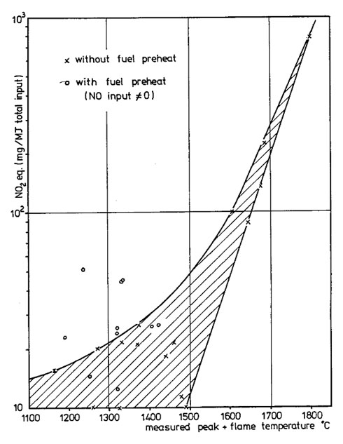
The relationship between NOx emissions and peak flame temperature are summarized in Figure 1 which may be used directly to estimate NOx emissions when the peak flame temperature is known.
In Figure 1, NOx emissions are expressed as mg NO2 per MJ total heat input, where the total heat input includes the heat in the fuel and the sensible heat input to the furnace through either air or BFG preheating (or both). NO2 is calculated as the NO2 equivalent of the NOx measured in the furnace flue gases.

Figure 1 – Relationship between NOx emissions and peak flame temperature for Blast Furnace Gas Flames with Benefaction
It maybe noted that the data collected using preheated BFG lie outside and above the shaded area suggested as the correlation. In this case, the NOx levels were affected by NOx formation in the BFG preheater (direct fired). It is unlikely that this phenomenon will affect flames where the BFG is preheated indirectly using a heat exchanger or regenerator.
3. What if I do not know the peak flame temperature?
If the peak flame temperature is unknown, it may be estimated from the [GLOSS]adiabatic flame temperature[/GLOSS] (CF251) using the relationship:
Peak flame temperature = Adiabatic temperature – 250 +/- 50
where all temperatures are in degrees C.
4. What are the limitations of this approach
The graphical method of Figure 1 should not be extrapolated beyond the range of peak flame temperatures measured in G1 and marked as experimental points on Figure 1.
Figure 1 should be applied with great caution if the furnace and flame conditions lie outside those studied during the G1 trials:
· Heat extraction to load 150 to 300 kW/m2
· Combustion intensity 60 to 120 kW/m3
· Excess oxygen 10%
· Air and/or fuel preheat up to 500oC
· Oxygen concentration in the [GLOSS]comburent[/GLOSS] from 21% (air) to 50% by volume
· BFG [GLOSS]Lower Calorific Value[/GLOSS] 2.3 to 3.1 MJ/kg
· [GLOSS]Natural Gas[/GLOSS] Lower Calorific Value 44 MJ/kg (7,2% inerts, 85% methane)
Acknowledgements
The author acknowledges the support and encouragement of Jean-Bernard Michel and Roy Payne during the adaptation of their original report to create this Combustion File.
Sources
[1] Michel J-B and Payne R. The use of blast furnace gas as a fuel in high temperature furnaces of the steel industry. Final report of the IFRF G1 trials, IFRF Doc No F01/a/100, March 1979.
