-
What are main characteristics of a black liquor recovery boiler?
Date posted:
-
-
Post Author
dev@edge.studio
1. Black liquor recovery boilers
[GLOSS]Black liquor[/GLOSS] (CF199) is the by-product of [GLOSS]chemical pulping[/GLOSS] and it is, after concentrating to firing conditions (65%-85% [GLOSS]dry solids[/GLOSS]), burned in large units called black liquor recovery boilers, Figure 1.
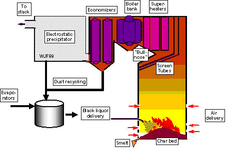
Figure 1. Schematic picture of a black liquor recovery boiler.
Black liquor recovery boilers are complex units which both recover the [GLOSS]inorganic cooking chemicals[/GLOSS] used in the [GLOSS]pulping process[/GLOSS] and make use of the chemical energy bound in the [GLOSS]organic[/GLOSS] portion of the liquor to generate steam. Though many differences exist between individual boiler designs, there are many similarities required by the process.
Foremost among these requirements is the need to have a stable, hot, [GLOSS]char bed[/GLOSS] in the bottom of the boiler for final combustion of black liquor char and for separation of the [GLOSS]inorganic smelt[/GLOSS].
Furthermore, heat transfer in the lower furnace occurs primarily through radiation, and through convection in the lower furnace necessitating the water wall construction for the boiler walls and the convective heat transfer section in the upper furnace.
Material and energy balances for one [GLOSS]kraft process[/GLOSS] black liquor and one operating condition reveal the complexity of the process itself, even on an input/output basis. The multiplicity of flows and the variety of chemical reactions are an inherent part of both extracting the energy and recovering the pulping chemicals in an environmentally friendly manner.
The most modern units are comparable to the size of conventional utility boilers. Capacity of recovery boilers are reported either as tons of dry solids per day (tds/day) or as energy output in (MJ) it varies in modern boilers between 1000 and 4000 tds/day (100-300MW steam).
The overall energy efficiency based on [GLOSS]higher heating value[/GLOSS] varies between 60 and 70% and is inherent in the fuel and pulping process. Biggest energy loss sources are water in black liquor, the endothermic reduction of oxidised sulphur compounds and [GLOSS]sensible heat[/GLOSS] of [GLOSS]black liquor smelt[/GLOSS]. Of these, the energy from combustion needed to evaporate the water in the fired black liquor can be positively influenced by firing black liquor at a higher dry solids content, which is the current trend.
2. Recovery boiler layout
In addition to the recovery boiler itself, the recovery boiler system consists of two more major components.
In the direction of the black liquor flow the evaporator plant is located before the recovery boiler. Here the weak liquor, as it is coming from the pulping process, is dewatered and the dry solid content is increased to levels between 65% and 85%.
Before going to the furnace both [GLOSS]carryover[/GLOSS] ash (from the hoppers) and the electrostatic precipitator dust together with make-up chemicals are added to the black liquor. The black liquor is then in the “as-fired” stage.
In combustion, the energy from the organic part is recovered in the water walls, super heaters, boiler bank and economisers whereas the inorganic constituents remain on the bottom of the furnace where the char carbon is converted to CO, leaving an inorganic smelt pool called the [GLOSS]smelt bed[/GLOSS] or char bed on the furnace floor.
The smelt leaves the boiler through openings ([GLOSS]smelt spouts[/GLOSS]) at the bottom, and is dissolved in weak [GLOSS]white liquor[/GLOSS]. This dissolving process leads to [GLOSS]green liquor[/GLOSS], which is returned to the [GLOSS]causticising[/GLOSS] plant where the chemical recovery process is completed. The [GLOSS]flue gases[/GLOSS] from the recovery boiler pass through an electrostatic precipitator ([GLOSS]ESP[/GLOSS]), to minimize the emission of particulates. These filtering devices are located just prior to the stack.
3. Recovery boiler equipment
Liquor guns deliver black liquor
Liquor guns are used to transport black liquor separate from the [GLOSS]combustion air[/GLOSS] into the recovery furnace. The liquor guns are located at an elevation of about 3-5 m above the floor of the furnace. Arrangements of several liquor guns are used to fire a recovery boiler with the actual number (2-16) depending on the size of the unit and the firing load and strategy.
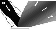
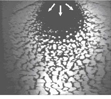
At the end of the gun is a liquor nozzle installed which spreads the liquor out so it covers a larger cross-section of the furnace. Several nozzle types are in use with the splash plate nozzle (Figure 2) being the most common one. It is designed so that the black liquor flow impinges on a flat plate after it leaves the nozzle. The impinging stream forms a wide, flat sheet of droplets (Figure 3) in which the mean droplet size is 2-3 mm, with smallest being less than 0.1mm nominal diameter the biggest over 5mm.
The combination of the angle of the gun and the angle of the plate determines the initial droplet trajectory and governs the contact between black liquor and air as well as it gives to a large extent the shape of the char bed.
The firing parameters also influence the amount of carryover ash that originates in the smallest burning black liquor droplets, and as the name indicates, are carried over to the heat surfaces by the flue gases.
Other black liquor nozzle types in use are conical spray nozzles, nozzles with an elliptical mouth and nozzles that inject the liquor with a swirling motion into the furnace. Nozzles are subject to heavily wearing conditions caused by the interaction of the corrosive black liquor and the hot furnace environment and need to be changed frequently on an almost weekly schedule.
|
|
|
|
Figure 2 Splash plate nozzle |
Figure 3. Photograph from above of a black liquor spray (courtesy of Helsinki University of Technology). |
Combustion Air System
The combustion air is directed separately from the black liquor into the furnace through air ports in which the air flow is controlled by dampers. The ports are laid out in horizontal rows located at several elevations up the furnace. Most commonly 3 to 4 air levels are in use, but recent designs use multi-air level systems with even 10 or more air port levels.
A classical three-level air system has the first air level located at bed height at about 1 m above the furnace floor. The second air level is located at approximately 2 m and the third level is located above the black liquor guns at around 8 m. Primary and secondary air ports are almost always located on all four walls, whereas the tertiary air ports are located mostly only on two opposing walls.
Air ports at the primary air level are always the smallest (0.05 by 0.25 m) and most numerous with up to 35 ports on one wall. The primary air is mainly used to form the shape of the char bed and to guarantee char burnout.
The airports on the secondary level are less in number (4-16 per wall) and typically larger than the primary air ports. This air level penetrates further into the furnace and controls the maximum bed height and the air injected burns away volatiles and CO.
There are up to 8 tertiary air ports located in most cases in the front and rear walls of the furnace. These air ports are usually the largest (0.15 by 0.75 m). The tertiary air system controls the final burnout of the combustion gases traveling upward and completes the combustion process.
Modern multi-air level systems can be designed to minimize carryover of liquor droplets upwards in the furnace and the NO emissions.
The Char Bed
The char bed is necessary for the reduction of oxidized sulphur species and the recovery of the inorganic material in the liquor. Char beds consist of carbon, partially pyrolysed black liquor solids and molten and frozen smelt.
Char beds typically cover the entire floor area. Many shapes have been observed, including low, flat beds, crater-shaped beds and steep beds up to 3 m high. The actual shape of the char bed is strongly depending on liquor spraying and the ratio of air distribution between the different air levels.
The main purposes of the char bed are to oxidize the remaining carbon in char and at the same time maximize the reduction of sodium sulphate or any other form of oxidised forms of sulphur to sodium sulphide.
The char bed temperatures are mainly between 800 and 1000°C and it is one main source of vaporization of sodium that condenses to fume particles in the colder parts of the furnace, finally ending up as the ESP dust.
Upper Furnace and Convective Heat Transfer Sections
In the upper furnace, located on the rear wall of the furnace, a so-called “bull nose” steers the gas flows into the superheaters. Its purpose is to protect the superheater section from direct furnace radiation and to direct the upward gas flow uniformly over the heat exchanger surfaces.
At the same location as the bull nose, screen tubes may be positioned over the entire depth of the furnace. Those screens should both lower the transport of carryover towards the convective section of the furnace and make the upward flow more uniform.
The convective heat transfer section of the boiler consists of the superheaters, boiler bank, and economizers. Even though heat transfer is dominated in this section by convection, the superheaters, located closest to the furnace, can be exposed to significant radiation.
Tubes in the convective section are widely spaced to accommodate the substantial carryover (0-5 g/mo3[GLOSS]dfg[/GLOSS].) of solid material transported from the lower furnace. This carryover, along with the high temperatures in this part of the boiler, leads to continuous deposition of material on the heat exchanger tubes. The deposition thickness is dependent of the amount of carry over but also to a large extent of the melting properties of the accumulated inorganic deposits containing different contents of Na, K, S and Cl.
Though large spacing between tube bundles is used and the automatic, retractable soot blower lances are continuously used in recovery boilers to minimize deposition and fouling in the convective heat transfer section, complete plugging of the convective section and a resulting shutdown of the boiler still is a common incidence in many cases.
In the boiler bank and economizers the main cause for possible fouling are the condensed fume particles. The total mass of fume particles (diameter < 1ìm) is much less than the mass of carry over particles (diameter 10 ìm -3mm) found in the super heater region. The contents of Na, K, S and Cl in the fume and carry-over are different and leads to different melting properties and makes the fume more problematic in the later heat surfaces, whereas carry over can mainly be problematic in the superheaters.
These effects makes fouling and deposition one of the critical features in a recovery boiler. For this reason, the heat transfer surface area in a recovery boiler is twice as much as that of a furnace burning a non-fouling fuel.
Recovery boiler steam temperatures are mainly not above 480°C but a few modern boilers have steam temperatures of 500°C. The steam pressures are around 90 bar and close to 110 bar, respectively.
Soot blowing steam is normally 1-2%, but in “difficult” cases it can even be above 5% of the produced steam. Carryover with subsequent fouling and the risk of corrosion of the superheater tubes and water walls are the main factors restricting the increasing of the steam numbers. The produced steam is mainly sufficient to both produce the electricity and the process steam needed at the pulp mill and in some cases electricity can also be sold to the grid.
4. Furnace conditions in a recovery boiler
The overall process of black liquor combustion requires the addition of heat and air to the black liquor droplets. The heat is required to dry and pyrolyse the liquor, while air is required for oxidizing the [GLOSS]pyrolysis[/GLOSS] gases and the organic part of the liquor.
The overall process is very similar to that of others fuels burned in utility boilers. However, two very unique aspects of recovery boilers are:
1) The air and fuel are introduced separately and;
2) The fuel is not finely divided.
This leads to several special issues to be addressed. Routine combustion of fossil fuels like coal, gas and oil sees the use of swirl burners in which nearly all of the air is introduced in the immediate vicinity of the fuel. This promotes rapid and complete mixing. In addition, liquid and solid fossil fuels are finely divided to increase the surface area available for heat and mass transfer; this shortens both ignition and final burnout times.
In strong contrast to this the fuel and air in a recovery boiler are introduced separately, and droplets are an order of magnitude larger than typical fossil fuel droplets and particles. The reasons for this involve the very high inorganic content of the liquor, the need to avoid entrainment towards the upper furnace, and the need to build a bed on the furnace floor to aid sulphur reduction and smelt removal.
Sources
T. N. Adams (Ed.), Kraft Recovery Boilers, Tappi Press, 1997.
J. Gullichsen, H. Paulapuro (Eds.), Papermaking Science and Technology – Chemical Pulping (Book 6B), Fapet Oy, 1999.