-
What is Flameless Combustion?
Date posted:
-
-
Post Author
dev@edge.studio
1. Background – conventional flame firing
In conventional combustion systems, a flame is formed in the stream of a combustible mixture of fuel and oxidant provided a steady [GLOSS]Flame front[/GLOSS] can be established. The sharp gradient of temperature and chemical composition across the flame front brings about a balance between fast chain-reactions due to high temperature, and quenching due to convection. Flame stabilisation is typically obtained by re-circulating hot and reactive combustion products and by favouring steep temperature and composition gradients. This is often achieved by fluid dynamic means ([GLOSS]Bluff-body[/GLOSS], [GLOSS]Swirl[/GLOSS] etc).
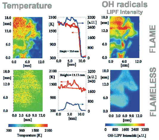
In the stationary flame front attached or close to the burner, optical and electrical effects can be detected and exploited for flame supervision. Examples are UV emission or ionisation detection. A picture of temperature and of [GLOSS]OH radical[/GLOSS] distribution in a conventional flame is reported in the upper half of Figure 1. The presence of a visible flame also gives indications to the furnace operator that all is well (or not as the case may be) with the combustion system.
In conventional flames, local gas temperatures can be quite high, approaching [GLOSS]Adiabatic flame temperature[/GLOSS] values in cases where the reaction occurs before there is considerable mixing with the furnace atmosphere surrounding the flame. Typical values are illustrated in the upper left quadrant of Figure 1: adiabatic temperatures for rich fuels easily range from ~ 1800 °C to well above 2000 °C, which can be observed in the hottest peak temperatures close to the flame front. Hot peak temperatures help effectively to stabilize the flame, but are the principle cause of the formation of [GLOSS]Nitrogen Oxides[/GLOSS] in flames by the [GLOSS]Thermal NO[/GLOSS] route and also cause unwanted non-uniformity of heat transfer rate.

Figure 1 – Temperature and OH concentration from laser diagnostic techniques
(upper half flame mode, lower half flameless mode)
2. Flameless combustion and its benefits
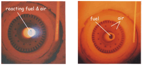
The flame-front combustion mode is the predominant firing mode in many industrial applications. It also occurs in natural and artificial fires. This mode is not, however, the only way of producing controlled combustion within a combustion chamber. In a high temperature chamber (reactants temperature > ~ 850 °C) and preferably using preheated air, a [GLOSS]Flameless combustion[/GLOSS] mode has been identified by deliberately suppressing a stable flame front. A comparison between flame and flameless mode is shown in Figure 2. In flameless mode, reactions take place at temperatures above the [GLOSS]Self-ignition temperature[/GLOSS], in a distributed large volume instead of being concentrated into a thin, highly convoluted and stretched flame front (Figure 1 – compare upper and lower half). With flameless combustion, there is no flame front, no visible flame, no UV or ionisation detection, and no noise or roar. CO and NOx are abated to very small residual values.
Reactants, at least locally, must be above self-ignition temperature for combustion to occur. This condition is accounted for in continuous furnaces that run constantly above ~ 850 °C (that is well above self-ignition): in such processes, flame supervision may be dispensed with according to safety rules, as there is no danger of the reaction extinguishing, and hence no risk of explosion. Therefore, once a process is safely above the fuel’s self-ignition temperature, the firing mode can be designed to deliberately avoid the onset of a burner-stabilised flame-front.

Figure 2 – Flame mode (left) and flameless mode (right)
The stability limits of flameless firing (see CF173) depend not only on temperature, but also on dilution of the reactants before combustion. The comburent or the fuel must be diluted in a large ballast of entrained inert flue gases composed of N2 + residual O2+ CO2 + H2O (the latter two coming from complete combustion itself). This [GLOSS]Inertisation[/GLOSS] of the comburent implies a substantial reduction of the local temperature after reaction well below the adiabatic temperature of the pure reactants.
3. How do I achieve flameless combustion?
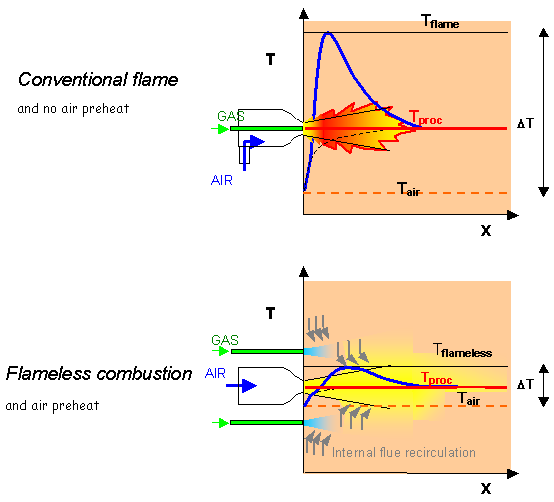
A good example is a [GLOSS]High velocity burner[/GLOSS], natural gas burner. In conventional firing, the fuel and air jets are placed inside a primary chamber to achieve early mixing between fuel and air and a stable flame. This is illustrated schematically in the upper half of Figure 3 that shows a flame stabilised in a conventional high velocity burner (using cold combustion air).
In the lower half of Figure 3, fuel is injected into the flue gases within the furnace space, away from the immediate vicinity of the combustion air. Similarly, combustion air is injected at high velocity into the chamber in direct contact with combustion products. Mixing between fuel gas and combustion products and between air and products takes place before mixing fuel gas and air (the process previously referred to as inertisation) and tends to bring temperatures close to the combustion products temperature. Then, provided the latter are above self-ignition temperature, flameless combustion occurs: no visible flame and no concentrated flame front is formed, but the combustion reactions occur in a large volume of the furnace space, where they proceed to completion.
It is important to note that the temperature profile is very much smoother in the flameless case (lower half of Figure 3). This is due to combustion occurring gradually while entraining more and more exhaust flue gases at process temperature. On the contrary, when using a conventional flame, there is little opportunity to entrain large amounts of flue gases upstream of the flame front, and hence to limit the peak temperatures in the reaction zone (upper half of Figure 3).
In Figure 3, air preheating (see CF172) is assumed for the flameless case (which is a preferred but not a necessary boundary condition): this is to stress how much the “DT”, i.e. the difference between minimum and maximum gas temperature, can be affected by the process. Large “DT”s imply large non uniformities in the profile of heat flux to the load, low “DT” means that the system tends to approach a [GLOSS]Well-stirred reactor[/GLOSS] at uniform temperature = Tproc.
The difference shown above is the basis of the exceptionally low NOx emissions of flameless firing (see CF174). It is also the key to the more widespread use of very highly preheated air. Air preheat temperatures of the order of ~ 800 – 1200 °C are possible with decentralised [GLOSS]Recuperator[/GLOSS] or with ceramic [GLOSS]Regenerator[/GLOSS] (see CF172). Flameless operation avoids very high peak-temperatures, occurring in conventional flames using such high pre-heats, and the risk of local material failures due to high local peak heat fluxes, while effectively curbing the formation of thermal NOx.

Figure 3 – High velocity gas burner: flame and flameless firing
The picture of Figure 3 is only one of the flameless firing patterns typical of furnaces that can be implemented with various arrangements of the air and fuel injection nozzles. Flameless combustion can be applied to other processes as well (e.g. steam generators, thermal treatment of refuse, gas turbine combustors etc..): the same basic principles and stability conditions (CF173) hold true, that is reactants temperature above self-ignition and dilution with a large ballast to keep down final reaction temperature.
4. What about lean fuels, oil and coal flames?
Flameless combustion is by no means limited to rich gaseous fuels such as natural gas, but can be applied as well to lean gaseous mixtures (such as fuel gases recovered from industrial processes) or to liquid and solid fuels. Figure 4 shows, once again by way of comparison, conventional and flameless firing of heavy oil with preheated, vitiated air.
In the case of Figure 4, right hand side, the inertisation and preheating of reactants, typical of flameless combustion, are carried out to a large degree, upstream of the burner because combustion air is vitiated (with inert gases) and preheated. Quite evidently, reaction steps follow chemistry paths different from the conventional, burner-stabilised flame and there is no wonder that pollutant formation and heat flux distribution are quite different. This may be exploited in practice for clean firing technologies and for improved process performance.

Figure 4 – Flame and flameless firing of heavy fuel oil
(left: flame mode, normal air at 250 °C – right: flameless, vitiated air O2 10% at 500 °C)
5. What are alternative names for flameless combustion?
Flameless combustion is recommended as a non-proprietary generic label identifying the phenomenon described above. Equivalent expressions are often used in practice, such as flameless oxidation and FLOX® , a registered trademark belonging to the company WS.
Furthermore, several different expressions are used to identify similar though not equivalent phenomena and techniques used for the same purposes. Examples of expressions found in the literature, including commercial trademarks, are:
- HTAC, (High Temperature Air Combustion – an unrigorous usage, since high temperature air combustors are not always flameless and vice-versa)
- mild combustion,
- dilute combustion
- Fuel Direct Injection (FDI – a process developed by Tokyo Gas Company)
- and others
Some of these refer to absence of a flame front, others to high air preheating, others to dilution of the fuel or vitiation of the comburent (O2 contents well below standard 21% by volume) before mixing etc. All these techniques tend to bring about very reduced “DT” and NOx emissions, and are based on inertisation of the reactants.
Sources
[1] J.A. Wünning, J.G. Wünning: Ten Years of Flameless Oxidation; Technical Applications and Potentials – 4th HTACG Symposium, Rome 26-28 November 2001
[2] T. Plessing, N. Peters, J.G. Wünning: Laseroptic investigation of highly preheated combustion with strong exhaust gas recirculation – Proc. Comb. Inst., 27,3197-3204,1998
[3] A. Milani, A. Saponaro: Diluted Combustion Technologies – IFRF Combustion Journal – Article 2001-01, February 2001
[4] J. Sudo, T. Hasegawa: Advanced HRS technology and its industrial applications – 4th HTACG Symposium, Rome 26-28 November 2001
