-
What is a gas-solids sampling Alcan probe?
Date posted:
-
-
-
Post Author
Neil Fricker
-
1. Background
When studying mixing and combustion in flames formed with non-gaseous fuels (see for example CF115), particularly solid fuels such as pulverised coals, waste or bio-fuels, it is often necessary to sample simultaneously for solids and gases on a point-by-point basis.
In order to acquire a representative sample, it is necessary to:
· Quench the gas phase reactions quickly;
· Use [GLOSS]isokinetic sampling[/GLOSS] techniques;
· Prevent any room temperature liquids present in the sampled gases (eg water vapour) from condensing within the probe, which may cause consequent problems for the composition of the sample and for the physical process of sampling (increased possibility of blockage)
The so-called Alcan probe for gas and low/medium concentration solids sampling is an example of a device that seeks to meet these criteria.
This sampling probe was developed to meet the specific requirements of a particular programme of research carried out by the IFRF, from which its commonly used name derives.
2. Principle of the ‘Alcan’ Gas/Solids Sampling Probe
The main features of the Alcan sampling probe are illustrated in Figure 1.
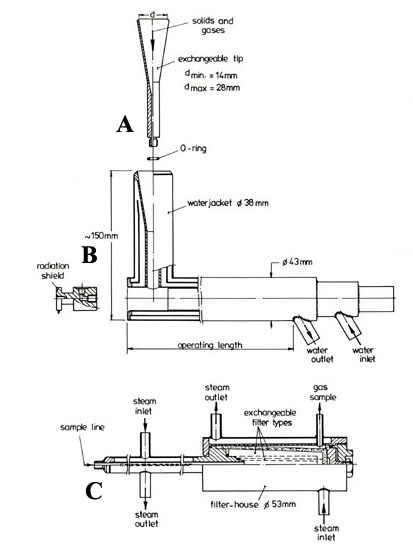
Figure 1. ‘Alcan’ gas/solids sampling probe – schematic
The first stage of the sampling is through an exchangeable convergent cooled tip.
The size of the nozzle and the sampling rate must be chosen to achieve isokinetic conditions at the probe entrance in order to collect a representative sample of the solids.
For the probe size illustrated, the inlet diameter of the quenching tube is normally selected to sample isokinetically with a suction rate in the neighbourhood of 5-10 l/min.
Prior measurement of local velocities (CF140, CF142, CF143) and temperatures (CF145) may be needed in order to establish the isokinetic condition.
Immediately after sampling, the flow of gases and solids is accelerated through the convergent section in order to achieve rapid cooling (quenching) of the sample within the cylindrical tube at the base of the nozzle.
The convergent section and the cylindrical part of the nozzle are cooled by direct contact with a similarly shaped water jacket within the tip of the main probe body.
This part of the probe must be designed to achieve a final sample temperature in the range 150-300oC. In this temperature range, most chemical constituents have ceased to evolve and the water vapour and other vapours in the sample do not condense.
The quenching time is of the order of 3 ms, which may be interpreted as a small displacement of the measuring point (less than 60 mm in most cases) with respect to the position of the sample nozzle entrance.
On leaving the sampling nozzle (A), the sample passes through a connector/radiation shield (B) into a steam heated or electrically traced sampling line which maintains its temperature as the sample travels to a filter unit at the rear of the probe.
At the downstream end of the sampling probe, an external steam heated or electrically traced filter unit is used to separate and collect the solids. In the diagram above, the “sample line” entry (C), on the left of the external filter unit is assembled such that it extends through to the end of the main probe, thus connecting with (B) the connector/radiation shield.
Exchangeable sintered bronze or ceramic filters are normally used to separate the solids from the gas stream. Ceramic filters are recommended for gas streams where reactions may occur on the surface of the bronze (e.g. gases containing SOx).
After sampling a measured volume of gas, the filter is removed before drying and weighing. The difference in weight between it and the clean dry filter then yields the mass concentration of solids in the sample. After removal from the filter, the solid sample may be subject to further analysis to determine its physical condition and chemical composition.
The cleaned gas sample passes out of the probe for independent analysis with downstream instrumentation (e.g. infra red gas analysers; gas chromatograph; mass spectrometer etc.).
3. Are there any constraints on the use of the Alcan probe?
This probe is not recommended for measurements in circumstances where NO may be converted to NO2 in the tip of the probe. For such measurements, a probe with a quartz-lined tip is recommended.
This probe is also not recommended for flows with high solids concentrations where direct water quenching is preferred.
4. Where can I find out more?
IFRF members may approach the IFRF Research Station for further details regarding the construction and use of the sampling probe described here.
Members and non-members may also purchase complete 43mm or 63mm outside diameter probes from the IFRF Station. This is often a cheaper and more effective option than designing and fabricating such probes from first principles.
Sources
[1] IFRF Doc No C76/y/1/5
[2] IFRF Technical Drawings IVO 83-02-28 and IVO 83-03-02