-
What are the stability limits of flameless combustion?
Date posted:
-
-
Post Author
espadmin
1. Background
Flameless combustion offers specific advantages over conventional flame firing (see CF171). When considering the stabilisation of a combustor in the [GLOSS]Flameless combustion[/GLOSS] mode, two conditions must be satisfied where the reaction is going to take place:
- The reactants must exceed [GLOSS]Self-ignition temperature[/GLOSS]
- The reactants must have entrained enough inert combustion products to reduce the final reaction temperature well below [GLOSS]Adiabatic flame temperature[/GLOSS], so much that a [GLOSS]Flame front[/GLOSS] can not be stabilised.
This Combustion File gives guidance on assessing a combustor against both these criteria.
2. How do I avoid forming a stable conventional flame?
For premixed fuel and [GLOSS]Comburent[/GLOSS], flammability limits can be determined experimentally for different fuel gases in standard air or in pure oxygen. Once a flame front is established in a turbulent flame, however, the local composition of the burning mixture is affected by entrainment of combustion products, consisting of inert components (N2+CO2+H2O + the residual excess O2).
The question of stability for a conventional flame is therefore best tackled considering three key partners in the process:
- Oxygen (the effective reaction partner in the comburent)
- Fuel gas (CH4 or H2 or CO or a mixture of hydrocarbon vapours etc )
- Inerts (basically a mixture N2+CO2+H2O)
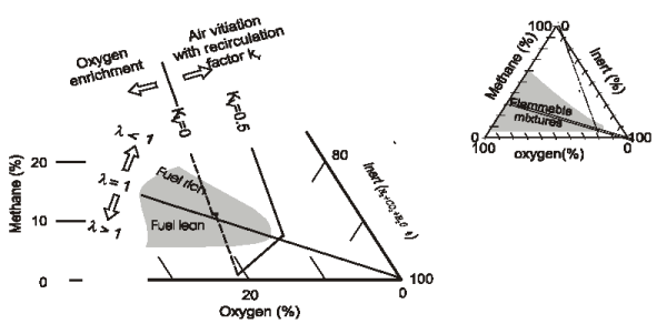
A triangular combustion diagram, having each of these three ¡°components¡± at each vertex, can be set up for the mixture before reaction, as in Figure 1.

Figure 1 – Triangular diagram for gaseous mixture
The diagram at the top right illustrates the flammability limits (shaded area) for methane. To run a flameless combustion system, the mixture fuel+O2+inert should avoid conditions inside the shaded area. The area of main interest for conventional and for flameless combustion is enlarged at the bottom left of figure 1.
With reference to Figure 1, a [GLOSS]Stoichiometric mixture[/GLOSS] of fuel and comburent lies on the line l = 1 connecting CH4 = 33.3% (1 mole methane in two moles pure O2) and the vertex “100% inert”. Combustion with [GLOSS]Standard air[/GLOSS] lies on the dotted line connecting the “100% methane” vertex with the point O2 = 21% on the oxygen axis; this is labelled Kv = 0 , where the recirculation factor Kv is :
Kv = moles of inerts /(moles of air+moles of fuel),
At any other value of Kv , other lines similar to the one labelled Kv = 0.5 can be calculated on the basis of simple reaction mass balance. These lines for constant Kv lie outside the flammability limits and are in operating conditions of interest for flameless combustion for Kv >~ 2-3.
It may be noted that for low oxygen concentration in the comburent (air vitiation), even a stoichiometric mixture will not support a stable conventional flame. Typically, it is hardly possible to stabilise a flame front if the oxygen concentration in the comburent is below <~~ 17% corresponding to Kv ~~ 0.30 flue gas re-circulation in combustion air.
This picture holds true at ambient temperature but the limits in the diagram get wider and ill defined when the temperature is increased. Nevertheless, the same qualitative principle will hold true also for fuels other than methane, although it may be necessary to determine the quantitative limits of flammability by means of tests for the particular fuels and circumstances of interest.
3. How do I ensure a stable flameless regime?
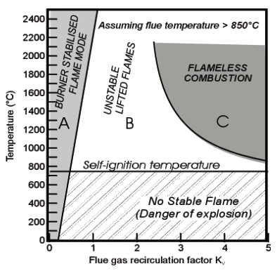
This situation is best appreciated in the following diagram showing Temperature (vertical axis) vs Recirculation Factor Kv as defined above (horizontal axis), where four regions can be identified (Figure 2):
- Conventional, flame-front stabilised flames are confined to Kv <~~ 0.30 (zone A in Figure 2)
- Below [GLOSS]Self-ignition temperature[/GLOSS], combustion reactions are quenched and cannot proceed further, unless special measures are taken to obtain a stable flame within the narrow stability limits quoted above (zone A)
- Above self-ignition, flameless combustion mode is possible if recirculation rate Kv is high enough (>~ 2-4), and temperature of the recirculated gases is high enough (see qualitative limits of zone C in Figure 2)
- A regime of [GLOSS]Lifted flame[/GLOSS] (zone B) can be identified between the flameless zone and the flame-front zone A; flames in lifted mode are irregularly dominated by fluctuations (see CF175) and this operating condition is best avoided.

Figure 2 ¨C Scheme of the combustion regimes (after WS GmbH)
Therefore for stable flameless combustion to occur, the mean reaction products temperature in the combustion chamber must exceed self-ignition and the recirculated mass of flue gases must exceed by a factor 2-4 or more the net mass produced by the reaction itself. It should noted that:
- The [GLOSS]Adiabatic flame temperature[/GLOSS] of the pure reactants, at least for rich fuels, is much higher (order of 2000 °C) than usual process temperature; with high Kv , the gas temperature after reaction will approach the temperature of the recirculated flue gases.
- The maximum value of the flameless reaction temperature, may be easily calculated with the same data used for adiabatic flame temperature computations
- Recirculation factors Kv ~ 2- 4 can be attained with high velocity burners on typical industrial furnaces, which makes possible implementing flameless combustion, provided anything that may cause a stabilised flame is avoided
- Recirculation flows and flow patterns may be estimated by the use of physical or mathematical models. The latter include CFD codes (CF43) and semi-empirical laws for enclosed jets (CF17)
Sources
[1] J. A. Wunning and J. G. Wunning – Flameless oxidation to reduce thermal NO-formation – Progress in Energy and Combustion Science, 23, 1997, #1, 81-94
