-
What are the principles behind the use of unidirectional probes for velocity measurements in furnaces?
Date posted:
-
-
Post Author
dev@edge.studio
Unidirectional probes for measurements of velocity are based upon the Bernoulli equation for an incompressible flow, which expresses the conversion of energy along a streamline in a perfect fluid (non-viscous and incompressible): where p is the fluid pressure (N/m2),
1. Background
 (1)
(1)
r is the fluid density (kg/m3),
g is the gravity constant (m/s2),
Z is the height of the measuring point (m),
V is the fluid velocity (m/s).
2. Principle
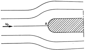
For a fluid element impinging on the stagnation point A on an obstacle placed in a uniform flow of velocity Vo (m/s), we may write the following:
 (2)
(2)
where PA is the pressure at the stagnation point (N/m2), and PS is the pressure in the flow at the same height.
It follows immediately that:
 (3)
(3)
Equation (3) is the principle upon which all unidirectional velocity probes are based.
3. Unidirectional velocity probes
Unidirectional velocity probes are a variant of the Pitot tube.
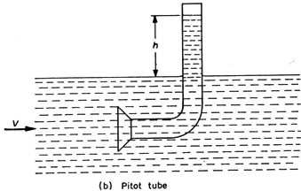 The Pitot tube was initially constructed for measurements of velocity in water and later used in flames. The probe was a simple tube bent at right angles facing the flow giving an over-pressure h (expressed as N/m2) above the free surface of the water such that:
 |
Unidirectional velocity probes are a variant of the Pitot tube.
 The Pitot tube was initially constructed for measurements of velocity in water and later used in flames. The probe was a simple tube bent at right angles facing the flow giving an over-pressure h (expressed as N/m2) above the free surface of the water such that:
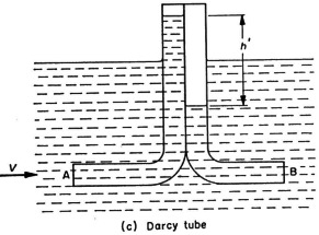
   (4) (4) Darcy improved this probe, by adding a second tube bent at right angles and facing downstream which measures the pressure, pB = k(rV2/2), so that the differential pressure between the two tubes is given by  (5) (5)which gives |
Here, a constant k, which has to be measured by calibration, is needed to determine the velocity V. For consistency with the units given above, h’ should be expressed in N/m2
To avoid determining the calibration constant k, Prandtl then proposed a probe, in which the constant k is not needed, by a judicious placing of the second static pressure tapping so that
 (7)
(7)
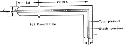
The probes that are generally used for the measurement of velocity in furnaces are Prandtl tubes or forms of this tube except for certain particular measurements which require more compact probes.
For measurements requiring a compact probe, a streamlined probe (illustrated in (e) below) is used, consisting of an upstream pressure tapping A and a downstream pressure tapping B such that:
 (8)
(8)
In this case, the constant k still has to be measured by a previous calibration.
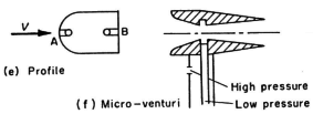
For low density fluids (hot gases) these probes have the disadvantage that they only give small pressure differentials. The sensitivity of the instrument may be increased by using a micro-venturi, for which the multiplication coefficient, which depends on a number of factors, has to be determined by calibration (illustration (f) above).
4. Applications
The velocity measuring probes describe above and their variants are used by the IFRF. The choice of probe depends on the particular measuring conditions such as hot or cold models, pulverised coal or oil fired furnaces.
For studies in cold models, finely constructed uncooled probes of small dimensions are used.
For measurements in the furnace, the probes need to be more robust, cooled by water or constructed out of refractory material and protected from condensation of water or oil vapour, and from the deposit of particles which can alter the characteristics of the probe and block the pressure hole (See CF142).
Sources
Industrial Flames, General Editors, Prof. J M Beér and Prof. M W Thring
Vol 1, Measurements in Flames by Chedaille and Y Braud.
