-
How do I design a velocity measurement probe according to the IFRF criteria?
Date posted:
-
-
Post Author
dev@edge.studio
 An important
parameter required in the construction of velocity measuring probes is the diameter d of
the pressure tapping in relation to D the diameter of the probe.
Experiments have shown
that for a tube with a hemispherical head there is no significant error when the ratio
d/D is between 0.2 and 0.74. For values of d/D less than 0.2 the position of the pressure tapping on the tube axis and the orientation of the tube along the velocity direction must be carefully adjusted in order to avoid measuring a pressure lower than the total pressure.
For values of d/D larger than 0.74, the disturbance of the flow by the tube becomes significant so that it becomes more difficult to measure the static pressure simultaneously with the total pressure.
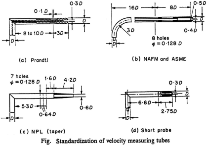
The ratio d/D has been fixed for different types of tube heads
according to the particular measuring conditions, as shown on the figure above. The position of the static pressure tappings on the tube depends upon the form of the tube head and the position of the support for the tube head.
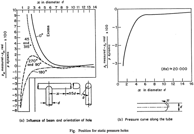
A number of experimental results such as those
plotted on the figure below have shown that static pressure should be measured by a number of holes uniformly distributed around the circumference of the tube and placed at a distance sufficiently far from the support of the probe head.

The pressure tapping has also to be sufficiently far from the head of the tube in order to measure effectively the static pressure, i.e. at a position where the streamlines are re-attached to the tube wall and where the velocity is equal to that of the measured velocity. For example, for a tube with a
hemispherical head of diameter D, the minimum distance is x = 2.5D. Standards have been fixed for the construction of tubes for which the constant k =
Dp/(rV2/2),
(wherein p, r and V are respectively the flow
pressure, the flow density and flow velocity,) remains equal to 1.
If any modifications are made to the probe it is necessary for the probe to be calibrated. This is the case, for example, for the streamlined tube
use at IJmuiden, or the sword blade tube which has been constructed for velocity measurements in regions where the Prandtl tube is too
cumbersome. The second pressure tapping is placed in the wake of the probe which is aligned perpendicular to the flow direction.

