-
How do I apply Particle Image Velocimetry in industrial flames?
Date posted:
-
-
Post Author
dev@edge.studio
1. Background of Particle Image Velocimetry
Particle Image Velocimetry (PIV) is a laser diagnostic method used for the measurement of instantaneous velocity fields in non reactive or reactive flows such as flames. It has been developed in parallel with laser sheet visualization (LSV) (CF 119 & CF 203). A specific experimental setup allows recording of couples of images, separated by a short time interval, of particles seeded in the flow. An instantaneous velocity field is then deduced from digital processing of each couple of images based on [GLOSS]cross-correlation[/GLOSS] calculations. More details on the PIV diagnostic can be found in CF 277.
The present Combustion File focuses on the application of Particle Image Velocimetry to a combustion facility of industrial scale. It is illustrated by an example of PIV measurements on a 1MW experimental boiler, performed in the framework of a collaboration between CORIA laboratory and Gaz de France – R&D Division [1]. This is, to our knowledge, the first implementation of this laser diagnostic on a combustion facility at an industrial scale.
2. Experimental setup at industrial scale
The main limitations of the application of PIV at industrial scale are
· the need of optical access to the combustion chamber
· the difficulty of seeding such large flows
· and the eventual presence of strong flame and wall radiation
Optical accesses
Based on dual laser tomography, the PIV technique requires first that a laser sheet crosses the flame, usually in a plane crossing its main axis, and second that particle images can be collected by a [GLOSS]CCD Camera[/GLOSS] set perpendicularly. For that, two optical accesses are needed.
In a horizontal combustion facility where the burner is set on the front side, one needs to implement an optical window on the rear side for the entrance of the laser beam in the combustion chamber. The specific optical arrangement of mirrors has also to be built to turn the laser beam toward the main axis of the flame through this window. Then, it is spread out to form a laser sheet, with a small width, thanks to spherical and cylindrical lenses. The focal length of the latter is chosen to adapt the size of the laser sheet to the dimensions of the flow inside the combustion chamber. Figure 1 presents a sketch of the PIV bench set up on the 1MW experimental boiler at Gaz de France- R&D centre.
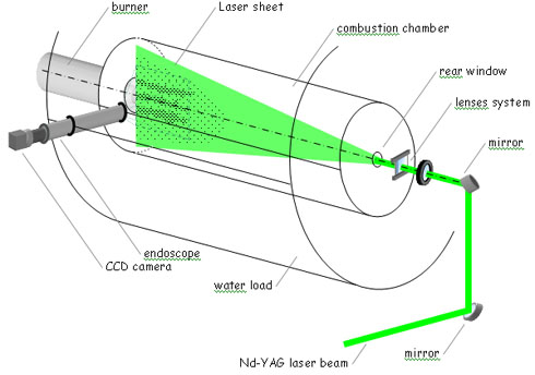
Figure 1. Diagram of the PIV setup adapted on a 1 MW experimental boiler
At industrial scale, the main difficulty is the optical access on the side wall of the facility for the acquisition of particle images on CCD camera. Indeed, this optical access has to be large enough to collect the widest part of the flow. Such a large optical window cannot operate in a high temperature environment without cooling. One easy way would be to leave open the access without any window, however such aperture has a strong impact on the local characteristics of the flow, which could have non negligible effect on the flame. Moreover, CCD cameras can not be set directly in front of the opened combustion chamber for long time periods. One solution for this second optical access is the use of a high temperature endoscope [1]. Figure 2 presents and example of an endoscope used for the application of PIV on an experimental 1MW boiler. It consists of a set of nine lenses, acting as an optical relay, surrounded by a water-cooled jacket. A nitrogen jet in front of the first lens is used for the thermal protection of the latter. The use of a zoom lens in front of the CCD camera allows one to adapt the field of view during the working of the combustion facility. In our example, the length of the endoscope has been designed to match the traversing of the water load of the boiler.
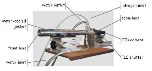
Figure 2. The high temperature endoscope equipped with a zoom lens,
FLC shutter and CCD camera for PIV measurements
Such an endoscope ensures that the combustion chamber remains sealed while allowing the CCD camera to operate in a friendly environment.
Application of PIV at such industrial scale requires the ability to measure large velocity fields. For this, a high energy source such as a bi-pulse [GLOSS]ND:YAG laser[/GLOSS] (400 mJ/pulse) and a camera with large dimensions of the CCD sensor (1280 x 1024 pixel² or more) should be chosen.
Flow seeding by fine particles
For PIV measurements in combustion, seeding of both fuel and air flows has to be performed with particles with specific characteristics. First, they have to be small enough to follow the turbulent flow. Second, they must be refractory so as to be still present in the flame. For that, aluminium oxides (Al2O3) or zirconium oxides (ZrO2) particles are usually used, with a typical granulometry in the range of 1 mm.
For example, in one industrial combustion facility, seeding of the flow was made thanks to homemade seeders put in by-pass of the main fuel and air supplies. Their design is based on laboratory models (fluidised bed, cyclonic seeder, rotary brush seeder, etc), with capacities adapted to the large scale.
Flame and wall radiation
Another problem encountered when performing velocity measurements by PIV in combustion is the natural flame emissions, corresponding to [GLOSS]chemiluminescence[/GLOSS] or soot radiation, which is superimposed on the images caused by the particle [GLOSS]Mie scattering[/GLOSS] signal [2]. In a furnace, radiation of high temperature walls can also be superimposed on images. Such a noisy signal induces bias on velocity measurements and has to be avoided on particle images. The common way to reduce it is to use an interference filter in front of the CCD camera, and for which the bandwidth is centred on the laser wavelength. However, this is not always sufficient. The other way to decrease flame radiation collection is to control the duration of the CCD illumination, and synchronise it with the laser pulses. Due to internal electronic design of CCD sensors, this can be done only on the first particle image (corresponding to the first laser pulse). An alternative solution is to use an external ferroelectric liquid crystal (FLC) shutter set between the camera and its lens (Figure 2). The moment and duration of the shutter opening are adjusted so that it includes each couple of laser pulses. This setup allows one to eliminate flame radiation on particle images, even without the need of an additional interference filter [1].
Another eventual noise signal on particle images comes from the laser itself. Indeed, when studying flow in the region close to the burner exit, the laser sheet may directly strike the burner and its support, which then induces strong reflections on the images. Because of the confinement of the flame in an industrial combustion chamber, reflected laser beams can also illuminate the walls, causing grey background on particle images. These additional signals induce a bias in cross-correlation calculations of particle images. It can be almost totally removed in a pre-processing step performed on each particle image before correlation calculation [3]. First, a mean background image is obtained from the calculation of the average of several images acquired without seeding of the flow. This image, comprising only the laser reflected signal without any particles, is considered as the reference background image. Then, subtraction of this reference image is processed on each raw particle image. Figures 3 a-c illustrate the improvement obtained with this simple pre-processing step on particle image acquired at the exit of the 1 MW boiler burner, where the laser reflection is the strongest. Such pre-processing step has to be tested and adapted for each experiment. For example, another improvement can be obtained by considering the average of particle images as the reference image, when it is necessary to take into account also the illumination of the background by the light scattered by the particles themselves.
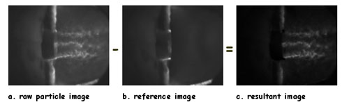
Figure 3. Background signal reduction on particle image by reference image subtraction
Particle images calibration
After acquisition, processing of the particle images can be made with the same algorithms as used in laboratory scale experiments to calculate particle displacements fields (CF 277). Corresponding velocity fields are then obtained from [GLOSS]magnification functions[/GLOSS]. These are determined by imaging a square grid pattern set in the plane of the laser sheet. However, such an installation is not obvious at an industrial scale. This has to be performed outside of the combustion chamber in the same optical configuration in order to determine magnification ratios. A real reference position in the flame can be deduced from particle images, for example by taking advantage of marks on the burner due to laser reflection.
For large angles of collection, barrel distortion can also be observed on images. In this case, magnification equations are no longer linear. Such [GLOSS]geometric distortion[/GLOSS] has to be taken into account on the scaling of the image as well as for the determination of velocity from particle displacements obtained by image correlation calculations [1].
3. Example of application on a 1 MW experimental boiler
The 1 MW experimental boiler of Gaz de France – R&D Division is based on a traditional two-pass industrial boiler, where the steam is produced from the water load surrounding the combustion chamber with a 1.2 tons/h nominal power output. This combustion chamber has been especially designed to enable in-flame measurements. In particular, access has been made through the water load to enable traversing of the high temperature endoscope (Figure 1). A commercial burner (Babcock Wanson LNTA0) has been tested during these experiments. A schematic of the burner is shown in the left part of Figure 4. Natural gas injection is performed through twelve finger-like injectors: nine are turned toward outside of the burner whereas three are turned inside. Air is supplied in the cylindrical duct, ending in a convergent form. A “flame arrester” is set behind the injectors. Its disk shape acts as a [GLOSS]bluff-body[/GLOSS] for the non-premixed flow, beginning the stabilization of the flame.
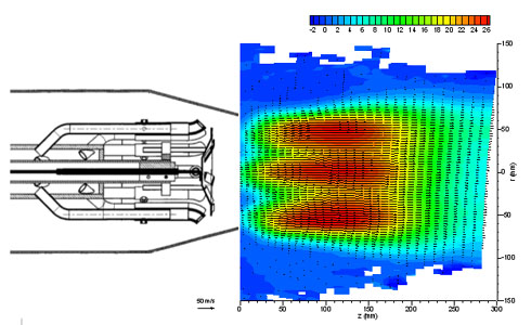
Figure 4. Mean velocity field obtained by PIV in the region close to the burner exit
(false colors = longitudinal velocity in m.s-1)
Figure 4 presents the mean velocity field, determined from the average of 495 instantaneous velocity fields obtained by PIV. At the exit of the burner, one clearly observes three separated jets due to the burner geometry. The central jet comes from the inner hole of the flame arrester, whereas the two others correspond to the annular flow between the disk and the convergent head. An [GLOSS]internal recirculation zone[/GLOSS] is also found, generated by the bluff-body effect of the flame arrester on the flow. This recirculation zone ensures the mixing of a part natural gas and air, and then the stabilization of the flame root. Then the jets merge together to form downstream the main flow, where the flame develops. This is an illustration of the potential of the PIV technique to point out aerodynamic characteristics of industrial flames. Moreover, as the velocity measurements are quantitative, PIV results can also be used for validation of Computational Fluid Dynamics (CFD) tools.
Acknowledgements
Application of PIV to the 1MW experimental boiler presented in this Combustion File has been made in the framework of collaboration between CORIA laboratory and Gaz de France – R&D Division, which support is gratefully acknowledged.
Sources
[1] D. Honoré, S. Maurel, A. Quinqueneau, “Particle Image Velocimetry in a semi-industrial 1 MW boiler”, Proceedings of the 4th International Symposium on Particle Image Velocimetry, Göttingen, Germany, Sept. 11-19, 2001.
[2] A. Stella, G. Guj, J. Kompenhans, M. Raffel, H. Richard, “Application of particle image velocimetry to combusting flows; design considerations and uncertainty assessment”, Experiments in Fluids, vol. 30, pp. 167-180, 2001.
[3] D. Honoré, B. Lecordier, A. Susset, D. Jaffré, M. Perrin, J.M. Most, M. Trinité, “Time resolved Particle Image Velocimetry in confined Bluff-Body burner flames”, Experiments in Fluids, vol.29, n°7, pp. S248-S254, 2000.