-
How do I achieve flameless combustion in practice?
Date posted:
-
-
Post Author
dev@edge.studio
1. Background: flame-front and flameless combustion
[GLOSS]Flameless combustion[/GLOSS] (CF171) techniques are typically applied to furnaces/processes above [GLOSS]self-ignition temperature[/GLOSS]: in many practical cases, this temperature coincides with the flameless threshold value of » 750 °C, above which no [GLOSS]flame detector[/GLOSS] is mandatory according to safety regulations for furnaces (CF214).
The reason is that:
– above this threshold no explosions are to be expected
– a mixture of fuel and oxidant reacts anyway, irrespective of proportion, without support of a flame front and with kinetics mainly dictated by temperature
In principle and in practice, it is easier to design and control a flameless system than a conventional stable flame burner: in the latter, the [GLOSS]flame front[/GLOSS] is almost a field discontinuity, depends on fluid dynamics (computationally difficult) and involves complex chemical reaction paths with abundant formation of radicals and intermediate products. The gradual, volume distributed reaction rate typical of flameless combustion and of [GLOSS]staging[/GLOSS] combustion is better controlled.
Often, flameless combustion is associated with very high air preheat (CF 172); with very hot air, the problem is not to stabilize a flame, but rather to postpone reaction by diluting the reactants. Reaction of pure air at » 1000 °C with natural gas generates adiabatic temperatures in excess of 2200 °C; the remedy consists in diluting the pure reactants with flue gases at process temperature. This thermal ballast will pick up the available heat and avoid noxious flame temperature peaks; a stable flameless regime can be established only with a consistent recirculation of combustion products as fully explained in CF 173.
Often, practical plants/systems undergo transition from cold state to a process temperature above threshold and there is no way of avoiding a dual system: the burner must be able to fire in flame mode below threshold and in flameless mode above threshold (CF214).
2. How do I design flameless combustion in practice?
The problem is to design dual burners that are capable of firing in both modes with the least design requirements and with easy switch-over. In many practical solutions, separate gas injection nozzles carry out switching from flame to flameless mode.

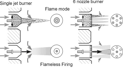
Figure 1 – Possible dual-mode solutions for high velocity burners
By way of example, Figure 1 compares flame firing (upper row) and flameless firing (lower row) in high velocity burners (air injection velocity > » 50 m/s). In both cases (single jet or multiple nozzle arrangement), flame mode is achieved by a primary flame inside a primary combustion chamber. This is stabilized by cross injection of gas and enough residence time to onset stationary primary firing. In both cases, flameless mode is carried out by central injection of gas at high velocity; no stationary flame front is then possible and combustion only occurs when mixing of three partners is carried out (that is, fuel + air and recirculated flue gases).

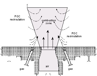
Flameless firing control relies on the accurate mixing pattern between fuel gas, air and recirculated flue gases; several mixing patterns can be envisaged (Figure 2), provided a large amount of recirculation entrainment (factor Kv: see CF173) is adopted, relying on high momentum to produce suitable kinetic energy for the mixing process.
The scheme of Figure 3 shows an arrangement of fuel injection separate from central air flow: with this design, flame mode can be achieved by injecting fuel into the central air jet upstream of the furnace wall and ignition of the mixture can be stabilized by a pilot flame. In flameless mode, fuel injection into the central air stream is stopped and only the gas injection ports besides the central air jet are used. This is a typical example of extreme fuel staging techniques envisaged for low NOx purposes.

Figure 3 – Gas injection for flameless firing
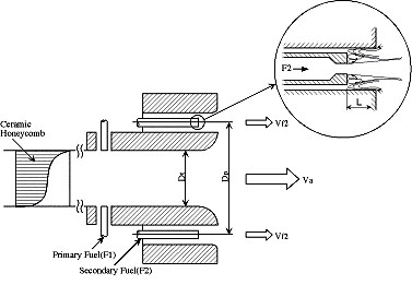
An alternative arrangement is shown on the following example of Figure 4: primary fuel is injected directly into hot combustion air giving rise to a stable flame front, while secondary fuel can be used for staging the flame and for flameless firing.

Figure 4 – Flame and flameless gas ports
The above examples refer mainly to standard gas-fired burners for furnaces: however, flameless combustion has been found to apply to other fuels (liquid and even coal) [4] and to combustion chambers other than a high temperature furnace (e.g. gas turbine combustors). In these cases, a particular design must be envisaged taking into account the general principles quoted in previous entries (CF171-173).
Reminder from IFRF Publisher: Some flameless burner design concepts have been protected by patents. Burner designers should be careful not to infringe proprietary rights when designing another burner. Patent owners should be contacted directly about licence agreements.
3. How do I control flameless operation in practice?
No flame or flameless system will remain strictly similar to itself during turndown, i.e. when the flow rate is reduced down to » < 25% of its nominal value (irrespective of air to fuel ratio control). This is basically due to fluid dynamics and to coupling with heat transfer: as a result, the turned-down flame will change pattern, will lift up due to buoyancy and will exhibit poor mixing, with typical yellow tips. Combustion control is lost when velocities get too small and comparable with natural draft.
Flameless firing is even more dependent on fluid dynamics than conventional flame firing and therefore has even less turn down capability. The best solution is to avoid modulated turn down at all; fortunately it is often possible to fire the burner, or many burners in a furnace zone, in an on-off mode or in using [GLOSS]sequential firing[/GLOSS].
Basically, this consists of controlling heat input by means of adjusting the time the burner(s) is(are) firing at full rate with respect to the shut off time. In the case of [GLOSS]regenerative burner[/GLOSS]s this is quite straight-forward since anyway burners are switched on and off for the basic heat recovery time by means of valves that are suitable for the on-off control.
Sources
[1] J. A. Wünning and J. G. Wünning – “Ten Years of Flameless Oxidation: Technical Applications and Potentials” – High Temperature Air Combustion and Gasification – Rome, Nov 2001
[2] J.Sudo and T. Hasegawa – Advanced HRS technology and its industrial applications – High Temperature Air Combustion and Gasification – Ibidem, Rome, Nov 2001
[3] J.Newby – “A review of the development and commercial application of the LNI technique”- High Temperature Air Combustion and Gasification – Ibidem, Rome, 2001
[4] R. Weber – “Combustion of Natural Gas, Oil and Coal with Air Preheated to Temperature in Excess of 1000 °C” – Ibidem – Rome, Nov 2001
