-
How can induced wakes be used to stabilise natural gas flames?
Date posted:
-
-
Post Author
dev@edge.studio
The relatively low flame speed of methane means that most natural gas flames are unstable when no particular precautions are taken. Depending on circumstances, there may be: It is, therefore, necessary to use a stabilising device. This can be one of the following: This Combustion File relates to the latter. An obstacle (often known as a bluff-body) is attached to the natural gas nozzle within the combustion air flow to create a wake. The axis of symmetry of the bluff body is parallel to the direction of the air flow. Figure 1: Stabilisation by effect of wake – technical arrangements
1. General
2. Burner geometry
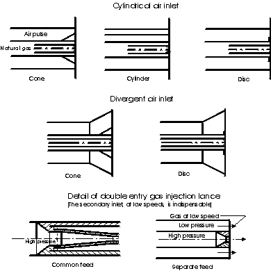
The combustion air can be supplied as an axial or as a divergent jet. The gas nozzle consists of:
- By means of an independent inlet at low pressure;
- By means of radial orifices upstream of the central injector and opening into the annular injector (close to the upstream end in the illustration).
We shall see the part played by the low velocity annular gas flow later. Its presence is essential to stabilise the flame using a wake.
3 Analysis of the stabilising action of a wake
3.1 Aerodynamic effects
The obstruction placed in the middle of the air flow generates a wake in which recirculation currents are produced due to the existence of a low pressure zone downstream of the flat front surface of the bluff body. As we move along the axis downstream from the bluff body, we find:
- A zone where the velocity is parallel to the axis and opposite in direction to the principal flow;
- A zone where the velocity is approximately perpendicular to the axis;
- A zone where the velocity moves progressively in the direction of the principal flow.
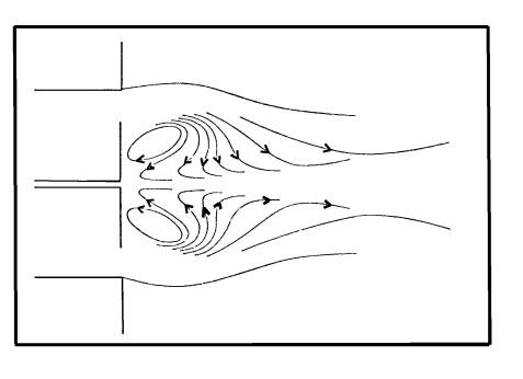
Figure 2: Flow downstream of a stabilisation disc with axial jet
| When the bluff body is placed in a cylindrical air inlet the length of the wake is the same size as the diameter of the downstream face of the obstruction. However, when the air inlet diverges, the length of the wake increases. It is approximately doubled when the total angle of the divergent air inlet is 65°. Whatever the shape of the combustion air inlet, a disc or a cylinder of the same diameter as the base of the cone produce a nearly identical wake volume. In the presence of an axial fuel jet, the wake is pierced by this jet and the reverse flow zone forms a torroid around the fuel jet. Fig. 2 shows the flow downstream of a thin disc. |
| When the bluff body is placed in a cylindrical air inlet the length of the wake is the same size as the diameter of the downstream face of the obstruction. However, when the air inlet diverges, the length of the wake increases. It is approximately doubled when the total angle of the divergent air inlet is 65°. Whatever the shape of the combustion air inlet, a disc or a cylinder of the same diameter as the base of the cone produce a nearly identical wake volume. In the presence of an axial fuel jet, the wake is pierced by this jet and the reverse flow zone forms a torroid around the fuel jet. Fig. 2 shows the flow downstream of a thin disc. |
|
3.2 Stabilisation mechanism
A tulip-like flame can, under certain conditions, arise in the bluff body wake. The main flame does not appear to be attached to the injector and its ignition begins approximately at the extremity of the wake.
The tulip flame is a diffusion flame the main role of which is to increase the temperature of the mixture found at the periphery of the central gas jet, so that it exceeds the ignition temperature. Once ignited, this flame is a permanent source of ignition for the main flame. In a cold furnace, it is necessary to ignite the tulip flame in the wake.
The tulip shaped flame is not created downstream of the bluff body unless secondary, low velocity gas flows into the wake. This local gas injection into the air rich recirculation currents of the wake creates the tulip diffusion flame. The gas flow injected into the wake need not necessarily be large; its mass flow can vary within fairly wide limits.
4. Performance and turn-down of wake induced flame stabilisation
For all stabilisation methods a relationship exists between two parameters, or two combinations of parameters, the representative curve of which is the boundary between the areas of stability and non-stability. All pairs of associated values on this boundary represent the stability limits (ie the performance) of the stabilisation method considered.
With regard to stabilisation by wakes, a relationship has been established between the limiting thrust for detachment of the central natural gas jet, the air velocity and the diameter of the downstream face of the bluff body. This relationship gives rise to a set of curves for different disc diameters (Fig. 3a).
In order to obtain a single curve representing the stability limits for all thermal inputs, bluff body sizes and combustion air velocities, we have plotted G/QD (the [GLOSS]specific thrust[/GLOSS] divided by the diameter of the downstream face of the bluff body), as a function of the variable V/D2 (the ratio of the air velocity to the square of the bluff body diameter).

Figure 3: Stabilisation by disc – stability limits
| A parabolic curve fit to the experimental points using the method of least squares, gives:
Where: G = gas jet thrust (N) Since the empirical relationship of equation (1) is based on tests made in cold free air using cylindrical air inlets, the flame stability in a hot furnace will always be better than that suggested by the equation. However, the value of the numerical coefficients depends on the specific characteristics of the natural gas employed. It is hoped that relationship (1) applies to natural gases containing a large proportion of methane. Experience shows that, all other things being equal, a the size of the bluff body required can be reduced by employing a divergent air inlet. Equation (1) can also be used to indicate the turn-down that one can hope to achieve with a given burner/ stabiliser geometry. |
5. Influence of bluff body stabilisation on the flame characteristics
Bluff body stabilisation has, in common with other stabilisation methods, the three following advantages:
- Modification of the position of maximum temperature along the flame;
- Possibility of influencing local mixing conditions;
- Elimination of the risk of flame extinction.
However, there are also effects that are specific to wake induced flame stabilisation. In particular, bluff body stabilised flames are not attached to the injector but sit at the end of the wake. At the root of the jet, the kinematic viscosity of the gas is relatively low and mixing is rapid. Ignition thus occurs at a point where the amount of oxygen induced by the natural gas jet is relatively high. The resultant intense combustion limits soot formation.
6. Practical application of the above properties
The preceding analysis may be used to design an effective flame stabiliser – an example is given in Combustion File 5 (see Related Combustion Files).
Sources
GEFGN; “Fiche technique sur la stabilisation des flammes de diffusion de gaz naturel par effet de silage”; Rev Gen Therm no 142, pp1071-1074 October 1973
Acknowledgements
This Combustion File has been extracted from the “Recueil Des Fiches Techniques” published in the Revue Generale de Thermique.
We are unaware of the original author’s name. However we would like to thank the author and Gaz de France for the use of the information.