-
How are traverse points selected for sampling air pollutants in undisturbed flows of flue gases?
Date posted:
-
-
-
Post Author
Patrick LaveryCombustion Industry News Editor
-
1. Background
Applicability
This Combustion File (CF) describes a method for determining the number and position of traverse points for air pollution sampling from stationary source undisturbed stack, duct and flue gases. By ‘undisturbed’ it is meant that the stack, duct and flue gases are at least a) 2 stack diameters downstream from any [GLOSS]flow disturbance[/GLOSS], and b) half a stack diameter upstream of a flow disturbance.
Ducts/stacks/flues can be rectangular, ellipsoidal or circular, but must have an [GLOSS]equivalent diameter[/GLOSS] of above or equal to 0.30m, or a cross sectional area not less than 0.07m2 – with areas less than this, flows are more uneven and traverse points are difficult to assign.
For traverse points for disturbed flows, see CF205. For a description of how to sample for trace metals and particulates, see CFs 206-209.
Furthermore, this method can be applied for both particulates traverse points and velocity traverse points.
2. Determination of number and location of traverse points
Selection of Measurement Site
It is most desirable to select a measurement cross-section at a site at least 8 stack/flue/duct diameters downstream and 2 diameters upstream of any flow disturbance. These are ‘primary quality’ sites. However, if this is not possible, the minimum distance is 2 stack/flue/duct diameters downstream and half a diameter upstream of any flow disturbance, constituting ‘secondary quality’ sites.
Minimum number of traverse points
For ‘primary quality’ measurement sites, the minimum number of traverse points for different types of stacks/ducts/flues is:
¨ 12, for circular/rectangular stacks with equivalent diameters above 0.61m.
¨ 9, for rectangular stacks with an equivalent diameter between 0.3m and 0.61m
¨ 8, for circular stacks with a diameter between 0.3m and 0.61m
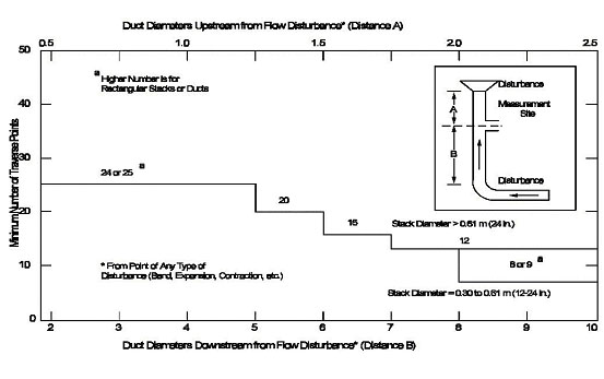
For ‘secondary quality’ measurement sites, Figure 1 should be used to find the number of traverse points.

Figure 1. Selection of number of traverse points for secondary quality measurement sites [Source: US Federal Registry]
Location of traverse points
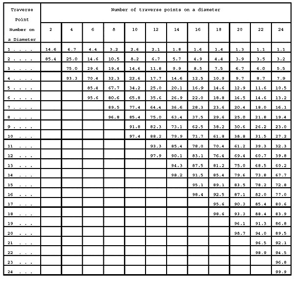
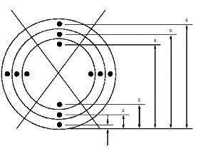
For circular flues/ducts/stacks, two perpendicular diameters should be used, with half of the total number of traverse points to be located on each diameter. Figure 2 should be referred to for obtaining the location of the traverse points determined. If, for instance, 8 traverse points are required, this is 4 on each diameter, so (looking at Figure 2) that the first should be 6.7% of the diameter along (starting from one edge), the second 25%, the third 75% and the last 93.3% (the points are mirrored on each side of the diameter). Figure 3 is a representation of the position of traverse points for circular stacks.
When determining traverse points for particulates sampling, one of the diameters should coincide with the axis likely to contain the most particulates (i.e., if the measurement site is downstream of a bend, then congruent to the bend).

Figure 2. Selection of position of traverse points for circular stacks [Source: US Federal Registry]

Figure 3. Positioning of traverse points for circular stacks [Source: US Federal Registry]
If this method yields locations within 2.5cm of a stack wall, for diameters above 0.61m, then the traverse point should be moved down the diameter so that it is at least that distance from the stack wall. For diameters equal to or less than 0.6m, this value is 1.3cm.
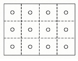
For rectangular stacks, the method is easier. Divide the rectangular cross section into smaller, equal sized areas, one for each traverse point, and locate the traverse point in the centroid of each area. An example is shown in Figure 4.

Figure 4. Positioning of traverse points for rectangular stacks [Source: US Federal Registry]
An unbalanced or expanded matrix using additional points for rectangular stacks can be used if required. Traverse points are not expected to be too close to stack walls for rectangular stacks.
Sources
[1]US EPA, US EPA Method 1: Sample and Velocity Traverses for Stationary Sources, US Federal Registry.
