-
How are traverse points selected for sampling air pollutants in disturbed flows of flue gases?
Date posted:
-
-
-
Post Author
Patrick LaveryCombustion Industry News Editor
-
1. Background
This method can be used to determine the location and number of traverse points for ‘disturbed’ flows in flues, ducts and stacks, for the sampling of air pollutants, such as particulates and trace metals. By ‘disturbed’, it is meant that the measurement site for the stack, duct and flue gases are less than a) 2 stack diameters downstream from any [GLOSS]flow disturbance[/GLOSS], or b) ½ a stack diameter upstream of a flow disturbance.
Additionally, this method is limited to ducts larger than 0.6m in diameter (or [GLOSS]equivalent diameter[/GLOSS]), when blockage and wall effects are minimal.
CF204 contains complimentary information on the location of traverse points.
2. Equipment
Two pieces of equipment are required for this method: a directional probe, a differential pressure gauge and an S-type Pitot tube.
The directional probe can be any probe capable of measuring both pitch and yaw angles of gas flows, such as a United Sensor Type DA 3D Directional Probe. It is prudent to engrave an identification number into the body of the probe. Immediately before use, the probe should be cleaned by back-purging with pressurised air, to unplug any plugging that may occur when used in flue gases with heavy particulate concentrations. The differential pressure gauge should be of water-column, inclined-vertical type, 254 mm (10 inches) , with 0.25 mm (0.01 inch) H2O divisions for the first 25 mm (1 inch) of the scale, then 2.54 mm divisions for the rest of the scale. However, if a) the arithmetic mean of all pressure readings at the traverse points is less than 1.27mm, or if b) 10% or more of the pressure readings are below 1.27mm, then a manometer of greater sensitivity should be used.
3. Method of selection of points
Essence of Method
The angle of the gas flow relative to the stack axis is determined with the use of a directional flow sensing probe, at around 40 points (see CF204) in the stack, to determine if the flow is too disturbed to sample at that measurement site or not.
If the measurement site is acceptable, then sampling can take place, using the same 40 or so traverse points used in this method.
Criteria
The measurement location is acceptable if Ravg £ 20° and Sd £ 10°, where Ravg is the average resultant angle of the flow relative to the axis of the stack, and Sd is the standard deviation of the relative angles measured.
Pitch and Yaw Angles
The direction of the flow can be described relative to the stack axis by the knowledge of two angles: the yaw angle and the pitch angle. These are illustrated in Figure 1. Figure 2 gives another representation of the stack axis and traverse line for clarity.
|
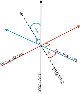 Figure 1. Representation of pitch angle (Pi) and yaw angle (Yi) relative to stack axis, traverse line and perpendicular. Planes are colour coded for added clarity. |
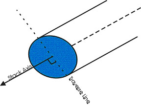
Figure 2. Traverse line relative to stack axis – occurs in the plane of the cross section of the stack. |
The pitch angle is the angle of the gas flow component in the plane that includes the traverse line and is parallel to the stack axis. The yaw angle is the angle of the gas flow component in the plane perpendicular to the traverse line at the traverse point and is measured from the line passing through the traverse point and parallel to the stack axis.
Calculations
First calculate the resultant angle (Ri) at each traverse point:
Ri = arc cosine [(cosine Yi)(cosine Pi)] (1)
Where Yi is the yaw angle of the flow relative to the stack axis for the traverse point in question, and Pi the relative pitch angle
Next calculate the average resultant for the measurements:
Ravg = S Ri/n (2)
Then calculate the standard deviations:
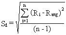
(3)
A spreadsheet is recommended for ease of repeatability of calculations.
Selection of points
Use a minimum of 40 traverse points for circular ducts and 42 points for rectangular ducts for the gas flow angle determinations. Follow the procedure in CF204 for the location and layout of the traverse points.
Measurement Procedure
Prepare the directional probe and differential pressure gauges as recommended by the manufacturer. Capillary tubing or surge tanks may be used to dampen pressure fluctuations. It is recommended, but not required, that a pretest leak check be conducted. To perform a leak check, pressurize or use suction on the impact opening until a reading of at least 7.6 cm (3 in.) H20 registers on the differential pressure gauge, then plug the impact opening. The pressure of a leak-free system will remain stable for at least 15 seconds.
Level and zero the manometers. Since the manometer level and zero may drift because of vibrations and temperature changes, periodically check the level and zero during the traverse.
Position the probe at the appropriate locations in the gas stream, and rotate until zero deflection is indicated for the yaw angle pressure gauge. Determine and record the yaw angle. Record the pressure gauge readings for the pitch angle, and determine the pitch angle from the calibration curve. Repeat this procedure for each traverse point. Complete a “back-purge” of the pressure lines and the impact openings prior to measurements of each traverse point.
Perform a post-test check, using the same method as the pre-test leak check described above. If the criteria for a leak-free system are not met, repair the equipment, and repeat the flow angle measurements.
Calibration
The directional probe must be calibrated before use. Calibration is performed in a test duct. If a circular test duct is used, the minimum diameter used should be 30.48 cm. For rectangular cross sections, the minimum side width should be 25.4 cm. The cross section of the duct should be constant for at least 10 duct diameters (or equivalent diameters). The test site should be eight diameters downstream and two diameters upstream of a flow disturbance.
In addition, the flow system shall have the capacity to generate two test-section velocities: one between 6.08 and 12.18 m/s (1,200 and 2,400 ft/min) and one between 12.18 and 18.33 m/s (2,400 and 3,600 ft/min).
Cut two entry ports in the test section. The axes through the entry ports shall be perpendicular to each other and intersect in the centroid of the test section. The ports should be elongated slots parallel to the axis of the test section and of sufficient length to allow measurement of pitch angles while maintaining the pitot head position at the test-section centroid. To facilitate alignment of the directional probe during calibration, the test section should be constructed of plexiglass or some other transparent material. All calibration measurements should be made at the same point in the test section, preferably at the centroid of the test section.
To ensure that the gas flow is parallel to the central axis of the test section, use the following procedure for cyclonic flow determination to measure the gas flow angles at the centroid of the test section from two test ports located 90° apart.
Level and zero the manometer. Connect a Type S pitot tube to the manometer and leak-check system. Position the Type S pitot tube at each traverse point, in succession, so that the planes of the face openings of the pitot tube are perpendicular to the stack cross-sectional plane; when the Type S pitot tube is in this position, it is at “0o reference.” Note the differential pressure p reading at each traverse point. If a null (zero) pitot reading is obtained at 0o reference at a given traverse point, an acceptable flow condition exists at that point.
If the pitot reading is not zero at 0o reference, rotate the pitot tube (up to ±90o yaw angle), until a null reading is obtained. Carefully determine and record the value of the rotation angle (è) to the nearest degree. After the null technique has been applied at each traverse point, calculate the average of the absolute values of è; assign è values of 0o to those points for which no rotation was required, and include these in the overall average. If the average value of è is greater than 20o, the overall flow condition in the stack is unacceptable. The gas flow angle measured in each port must be ± 2° of 0°. Straightening vanes should be installed, if necessary, to meet this criterion.
Pitch Angle Calibration
Perform a calibration traverse according to the manufacturer’s recommended protocol in 5° increments for angles from -60° to +60° at one velocity in each of the two ranges specified above. Average the pressure ratio values obtained for each angle in the two flow ranges, and plot a calibration curve with the average values of the pressure ratio (or other suitable measurement factor as recommended by the manufacturer) versus the pitch angle. Draw a smooth line through the data points. Plot also the data values for each traverse point. Determine the differences between the measured data values and the angle from the calibration curve at the same pressure ratio. The difference at each comparison must be within 2° for angles between 0° and 40° and within 3° for angles between 40° and 60°.
Yaw Angle Calibration
Mark the three-dimensional probe to allow the determination of the yaw position of the probe. This is usually a line extending the length of the probe and aligned with the impact opening. To determine the accuracy of measurements of the yaw angle, only the zero or null position need be calibrated as follows: Place the directional probe in the test section, and rotate the probe until the zero position is found. With a protractor or other angle measuring device, measure the angle indicated by the yaw angle indicator on the three-dimensional probe. This should be within 2° of 0°. Repeat this measurement for any other points along the length of the pitot where yaw angle measurements could be read in order to account for variations in the pitot markings used to indicate pitot head positions.
Sources
[1]US EPA, US EPA Method 1: Sample and Velocity Traverses for Stationary Sources, US Federal Registry.
[2]US EPA, US EPA Method 2: Determination Of Stack Gas Velocity and Volumetric Flow Rate, US Federal Registry.