-
How do I model coal char particle combustion in oxy-fuel atmosphere?
Date posted:
-
-
Post Author
dev@edge.studio
1. Background
There are several models available describing [GLOSS]char[/GLOSS] particle oxidation under air-fired conditions, and some of them can also be used successfully for coal char particle combustion modelling in [GLOSS]oxy-fuel[/GLOSS] atmospheres. The most common are:
– Apparent Reactivity model [1]
– Intrinsic Reactivity model [2]
– Char Burnout Kinetic model [3]
– Physical model [4]
– Semi-global model [5].
Most [GLOSS]CFD[/GLOSS] codes use the apparent reactivity model thanks to its simplicity and sufficient accuracy. With some modifications, this model is suitable for use in [GLOSS]oxy-coal[/GLOSS] flames. This modified version of the apparent reactivity model is presented below.
2. Modified apparent reactivity char combustion model for oxy-coal applications
The combustion mechanism of coal char in an oxy-fuel atmosphere should be extended from that in air by the adding of two additional surface reactions (with CO2 and H2O, which can be present in the combustion system at high concentrations), so that it would compose of the following reactions:
2C(s)+O2=CO2 (R1)
C(s)+CO2=2CO (R2)
C(s)+H2O=H2+CO (R3)
It is assumed that the reactions do not compete with each other and the total coal char consumption rate is the sum of their reactions rates.
The model assumptions are that the combustion process can be controlled by reagent (O2, CO2 or H2O) diffusion to the particle surface and that the surface reaction depends on the:
– rate of reagent diffusion through the boundary layer to the particle surface
– reaction rate on the particle surface.
Reaction rate of the i-th reaction is expressed in the form:

where:
rc,i ¨C rate of the i-th reaction, kg/s
mp ¨C particle mass, kg
t ¨C residence time, s
¦×i ¨C stoichiometric factor for i-th reaction, –
dp ¨C particle diameter, m
¦Ñp ¨C particle apparent density, kg/m3
R ¨C gas constant, J/moleK
Tp ¨C particle temperature, K
Yg,i ¨C i-th reagent gas mole fraction in the bulk gas, –
Mg,i ¨C molecular weight of the i-th reagent gas, kg/kmole
kd,i ¨C diffusion rate constant of the i-th reaction, kg/m2sPa
kc,i ¨C kinetic rate constant of the i-th reaction, kg/m2sPa
The diffusion rate coefficient is expressed by:

where:
D0,i ¨C binary diffusion coefficient of the i-th reagent gas in the bulk gas at T0, m2/s
Tg ¨C bulk gas temperature, K
T0 ¨C reference average temperature between bulk gas and particle, K
The kinetic rate coefficient can be expressed in the Arrhenius form:

where:
Aa,i – pre-exponential factor of the i-th reaction, kg/m2sPa
Ea,i ¨C apparent activation energy of the i-th reaction, J/mole
The change of the particle size follows the expression:

where:
dp,0 ¨C initial particle diameter, m
X ¨C conversion (burnout), –
¦Á ¨C a coefficient depending on the combustion regime (here 0-0.33)
In case of reactions R2 and R3, the combustion rate is completely kinetically controlled [6], so the reaction rates of reactions R2 and R3 are in form:

It may be necessary to accurately determine all the required kinetic parameters of all the active reactions, since they heavily depend on the coal type and operating conditions. In order to do so, it is necessary to undertake char combustion experiments under oxy-fuel conditions following the procedure described in CF312 and to derive the kinetic parameters according to the CFD-optimisation hybrid method described below.
3. Kinetic parameters derivation
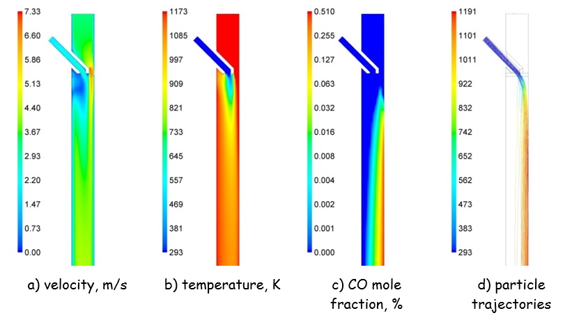
One of the most important pieces of information required for an accurate determination of the kinetic parameters is the [GLOSS]thermal history[/GLOSS] of the particle in the reactor. Thus it is firmly advised to perform CFD simulations representing the experimental conditions adopted during the oxy-fuel coal char combustion tests using the relevant reaction kinetic parameters available from literature or the [GLOSS]OFDB[/GLOSS]. This would enable the obtainment of crucial information about the particle residence times and temperatures during experimental tests, which are, along with the burnout, the input for the optimisation process of kinetic parameters. Figure 1 presents some example results of CFD modelling of coal char combustion in DTF under oxy-fuel conditions, which demonstrate non-uniformity in the gas and particles¡¯ velocities and temperatures, which needs to be accounted for.

Figure 1: Selected CFD modelling results of pulverized char combustion in the drop tube furnace under oxy-fuel conditions of Tf,¡Þ = 1173 K, yO2,¡Þ = 3%. Particle trajectories, (d), coloured by particle temperature in K [6]. |
Once the particle thermal histories are determined it is recommended to derive the kinetic parameters for each active reaction in the combustion system adapting one of the available methods of the optimising the function:

3. Conclusion
A modified apparent reactivity char combustion model can be successfully used to predict coal char combustion conversion under oxy-fuel combustion conditions. The required kinetic parameters can be obtained using an [GLOSS]IPFR[/GLOSS]/[GLOSS]DTF[/GLOSS] able to perform tests in conditions comparable to full-scale pulverised fuel boilers.
Sources
[4] Haas J.H.P., Lockermann S. A., van de KAMP W. L., Combustion characterization for a suite of different coals. Final report on CC8 Experiments, IFRF Doc. No. F 37/y/35, 1995.
[6] Hercog J., Lewtak R., Experimental and numerical investigation of coal char combustion process under standard and oxy-fuel conditions, 39rd International Technical Conference on Coal Utilization and Fuel Systems, Clearwater, FL, USA, 2014.
Acknowledgements
The research leading to these results has received funding from the European Community’s Seventh Framework Programme (FP7/2007-2013) under grant agreement n¡ã 268191.
