-
What is CFD for combustion calculations?
Date posted:
-
-
Post Author
dev@edge.studio
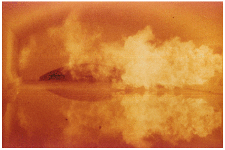
[GLOSS]Computational Fluid Dynamics[/GLOSS] (CFD) is presently regarded as a valued tool for the analysis of fluid-flow and heat related problems. In practically all branches of engineering, CFD is used for: CFD provides simulations that can be used for evaluation, critical examination and optimisation during the complete design process. In addition, potential benefits (or drawbacks) of “conceptual” modifications during a phase of optimisation can be evaluated before being actually implemented on site. It is particularly suitable to simulate new, ‘thought’ processes and experiments, all at much lower costs and shorter time than is possible by conventional trial-and-error methods and laboratory or pilot experiment. CFD also allows to qualify/quantify, before implementation, the impact of changes in operational conditions within a given combustor – for example the [GLOSS]Combustion[/GLOSS] systems utilised in glass melting, exemplified in Figure 1. Figure 1 Flames in a Glass Tank CFD is a Mathematical Modelling technique which, following a given pattern, solves iteratively a set of conservation equations (such as mass, momentum, heat… ) or modelling equations (i.e. [GLOSS]Turbulence[/GLOSS]… See for example
1. Introduction

2. What is CFD?
Its outcome yields information on the: velocity fields, pressure gradients, temperature distributions, species concentration contours, burnout levels, solid loading or particle tracks, …etc.
CFD in practise:
In the initial design phase of, for examples a boiler or industrial furnace/oven, attempts are made to maximise the efficiency and minimise the emissions. It is therefore necessary for the designer to consider the geometry, fuel distribution and composition, mixing effectiveness of the air systems and overall heat transfers. CFD can accelerate the optimisation of the design parameters, providing complementary information and allowing a more thorough examination of the design space.
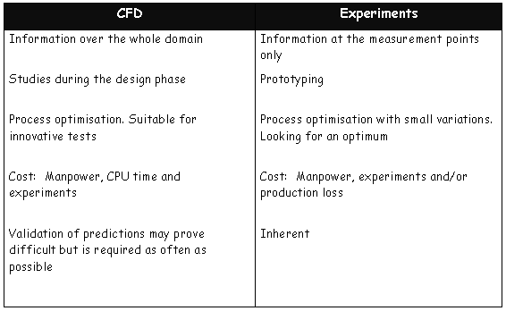
Numerical modelling has advantages over physical modelling in that actual geometric scales and temperatures are used. Comparison between a CFD and an experimental approach is illustrated in Table 1.
Advantages over field data based study include the ability quickly and cheaply to analyse a variety of design options without actually modifying the system, and the availability of significantly more data to analyse the results. Costs to perform a numerical study are generally a fraction of the cost to set-up a physical flow model, and are therefore significantly lower than the cost of a field study. However, CFD predictions require validation at all possible stages and this may prove arduous.
Table 1: Comparison between CFD analysis and experiments

CFD and time-scale
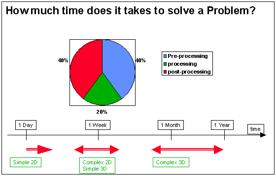
The time necessary to solve an industrial problem is extremely dependent on the level of complexity and accuracy required. If the problem can be simplified and the flow assumed to be two-dimensional, then a CFD analysis can be as short as one day. However, the set-up and computational times significantly increase as soon as the amount of details gets larger.
For complex three dimensional problems, including sub-model development, analysis of the results and parametric study, the time necessary to solve a problem can even reach one year. Figure 2 gives an overview on a typical time/complexity scale.
This figure shows as well the time distribution between pre-processing, processing and post-processing. The increase of the computational power tends to reduce the processing time, although CFD engineers tend to increase the level of details encompassed in a model.
Pre-processing, which is the time needed to collect the data, generate a computational grid and set-up the problem remains a significant part of the study.
Good grid generation is essential to minimise the risk of numerical hazards and to ensure predictive quality.
Post-processing, which stands for proper analysis of the results and reporting should not be neglected. This evaluation time generally increases with the problem complexity.

Figure 2 Typical time scale required by a CFD analysis
At the beginning of the design phase of a new installation, there is a need for very fast models in order rapidly to make a trade-off among a large number of configurations. At this stage, use of Macroscopic Models is usually preferred to heavy CFD calculations.
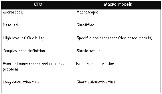
As soon as the main design is outlined, CFD is applied for more detailed design. A comparison between macro models and CFD is shown in Table 2.
Table 2: Comparison between CFD models and macroscopic models.

Conclusions
Computational Fluid Dynamics is a very powerful tool for design and process optimisation, provided that proper validation is obtained where appropriate.
It requires experience in order to efficiently set-up a problem, as well as to analyse the results.
Best practise would recommend that predictive outcomes/choices are also constructively reviewed and discussed with other involved parties.
